National Crane 03-20-2019 Control # 613-06 7-3
NBT30H-2 SERVICE MANUAL OUTRIGGERS
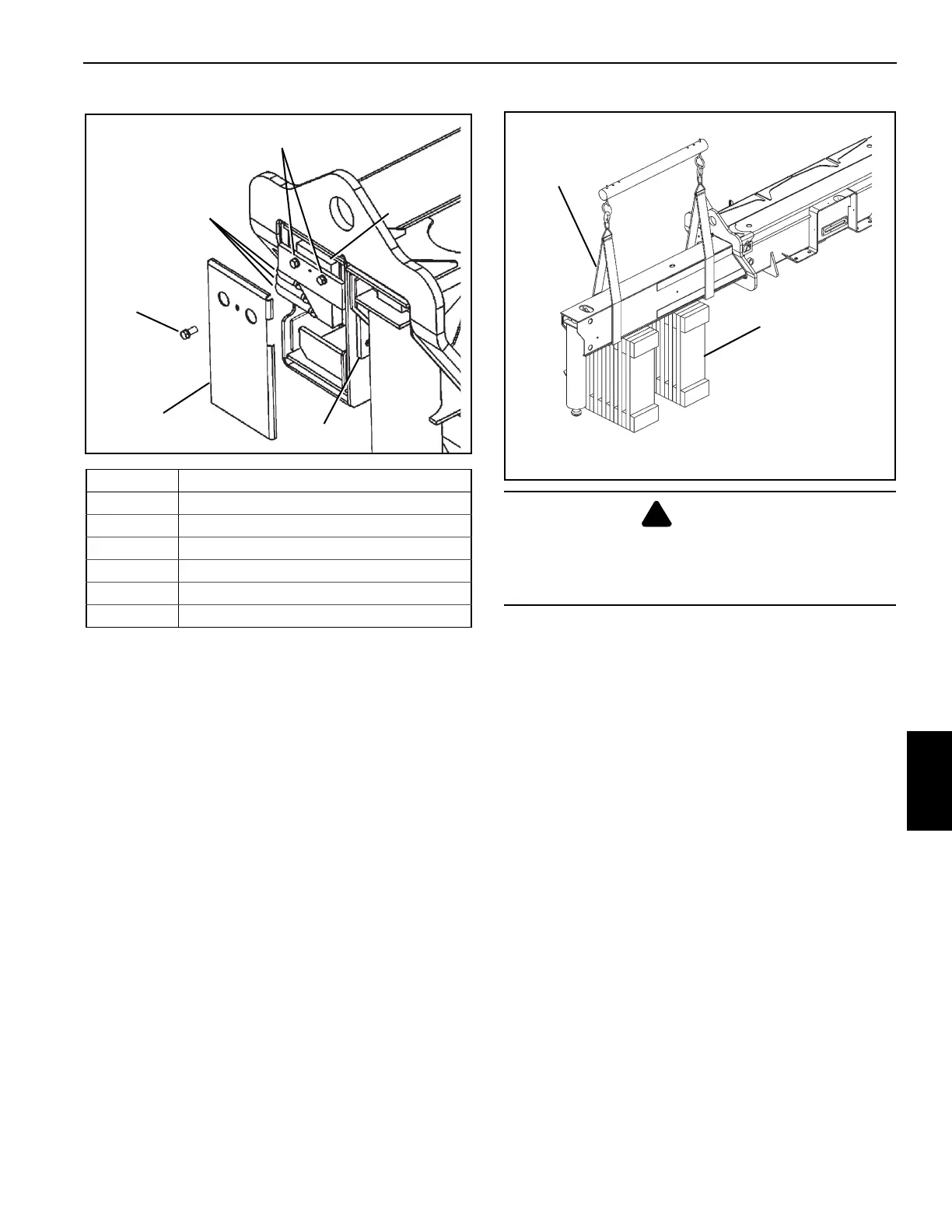
4. Unbolt and remove the end plate.
5. Tag and remove the hydraulic tubes at the end of the
outrigger box (Figure 7-3).
6. Remove the extension cylinder bolts and lower the base
of the extension cylinder to the bottom of the outrigger
beam.
7. Remove the wear pad set screws in the top of the
outrigger beam and back off the top wear pads (7)
(Figure 7-1).
8. Place blocking material under the outrigger beam
(Figure 7-4).
9. Pull the outrigger beam out of the outrigger box with the
lifting device.
10. Position the outrigger beam on the blocking material.
Inspection
Inspect the outrigger beam for bends, evidence of cracks, or
other damage. Check the outrigger beam internally for
hydraulic fluid, which may indicate a leaking cylinder, loose
connection, or damaged hydraulic line.
Outrigger Beam Installation
1. Apply grease (EP-MPG) to the bottom of the outrigger
beam.
2. Apply anti-seize to wear pad and set screw threads.
3. Adjust the bottom wear pads on the outrigger box until
about 6.4 mm (0.25 in) is protruding. This keeps the
beam off of the bottom of the outrigger box.
4. Slide the beam into the outrigger box.
5. Align the base of the extension cylinder barrel with the
holes in the end of the outrigger box.
6. Bolt the extension cylinder to the end of the outrigger
box with the two bolts.
7. Reconnect the hydraulic lines as per removal tags.
FIGURE 7-3
3
4
6
1
5
2
Item Component
1
Outrigger End Plate
2 End Plate Bolt
3
Outrigger Hydraulic Tubes
4 Extension Cylinder Bolts
5 Barrel End of Extension Cylinder
6 Nonadjustable Wear Pad
DANGER
Crushing Hazard!
Blocking material must be able to support the outrigger
beam and not allow the beam to tilt or slide.
Blocking material
must be capable of
supporting the
outrigger beam.
Use lifting
straps. Do not
use chains.
FIGURE 7-4

 Loading...


