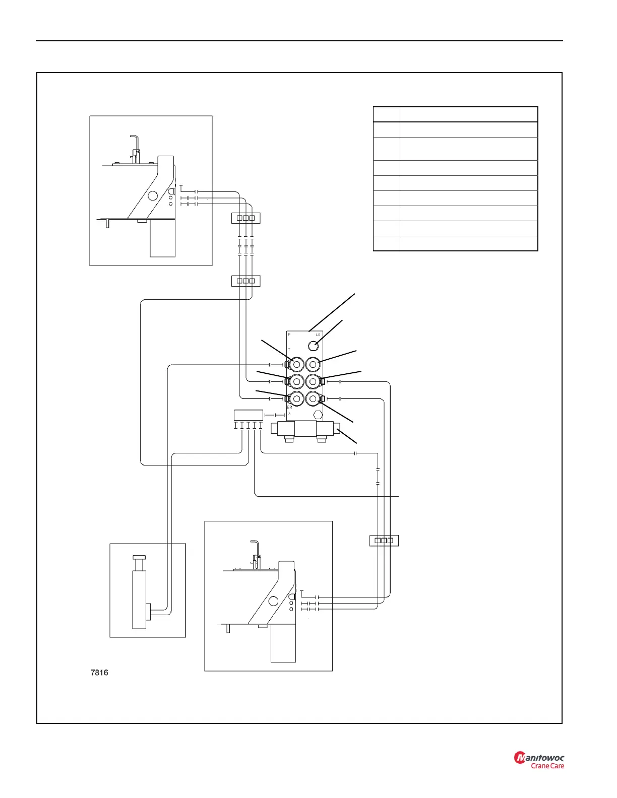
To Rear Outriggers
• Outrigger beam and
stabilizer are on the right.
• Hydraulic line hookup is
on the left side.
R = Retract
JE = Jack Extend
BE = Beam Extend
Right Front Outrigger
R
JE
BE
• Outrigger beam and stabilizer are on the left.
• Hydraulic line hookup is on the right side.
Left Front Outrigger
1
5
2
3
4
6
7
Front Outrigger
Manifold
Item Solenoid
1 Outrigger Enable
2 Center Front Outrigger (SFO)
(Optional)
3 Passenger Side Stabilizer (Right)
4 Passenger Side Beam (Right)
5 Driver Side Beam (Left)
6 Driver Side Stabilizer (Left)
7 Extend/Retract
8 Beam Extend Relief
NOTE: See page 3-7 for front
outrigger manifold detail.
Center Front Jack
(SFO) Optional
Extend
Retract
FIGURE 9-24
Front Outrigger Hydraulic Line Connections
To Ta n k
8
R
JE
BE

 Loading...


