ELECTRIC SYSTEM NBT30H-2 SERVICE MANUAL
3-10 03-20-2019 Control # 613-06
RCL COMMUNICATION OVERVIEW
The RCL needs to communicate with the various sensors,
switches, and transducers on the crane in order to perform
the RCL functions. The RCL uses Controlled Area Network
(CAN) bus communications.
Each device on the CAN network is capable of digital
communications. This enables many devices to
communicate quickly over a single twisted pair of wires.
Each device on the CANbus sends and/or receives
messages on the network in a predefined format called a
protocol. A device is called a node and one of the nodes is
defined as the RCL Master Module.
Information is sent over a main CAN line which has a
maximum length of 40 meters. Each node has a drop line off
the main CAN line and the maximum length of the drop line is
about 1 m (3.28 ft).
The transmission of messages is broadcast over the network
to all nodes. Only the node or nodes to which the message is
intended responds to the transmission. All other nodes
ignore the message.
Advantages to a CANBUS system are:
• Reliability
• Self diagnostics
• Ease of Installation
• Elimination of a large bundle of wires
• Down loading to a laptop computer
• Protected safety interlocks
• EMI/RFI tolerant
RCL CANBUS
The RCL has the following Nodes on the CANbus:
• RCL Master Module
• RCL Display Module
• RCL Sensors
• Radio Remote Module (Optional)
• Throttle Module (Optional)
All nodes on the RCL CANbus both receive and transmit
messages. There is 120 ohm termination resistor on each
end of the main CAN line. The resistors are in parallel and
when the main CAN line is measured across the terminals
the resistance should read 60 ohms.
NOTE: When measuring resistance there should not be
power to the CAN line.
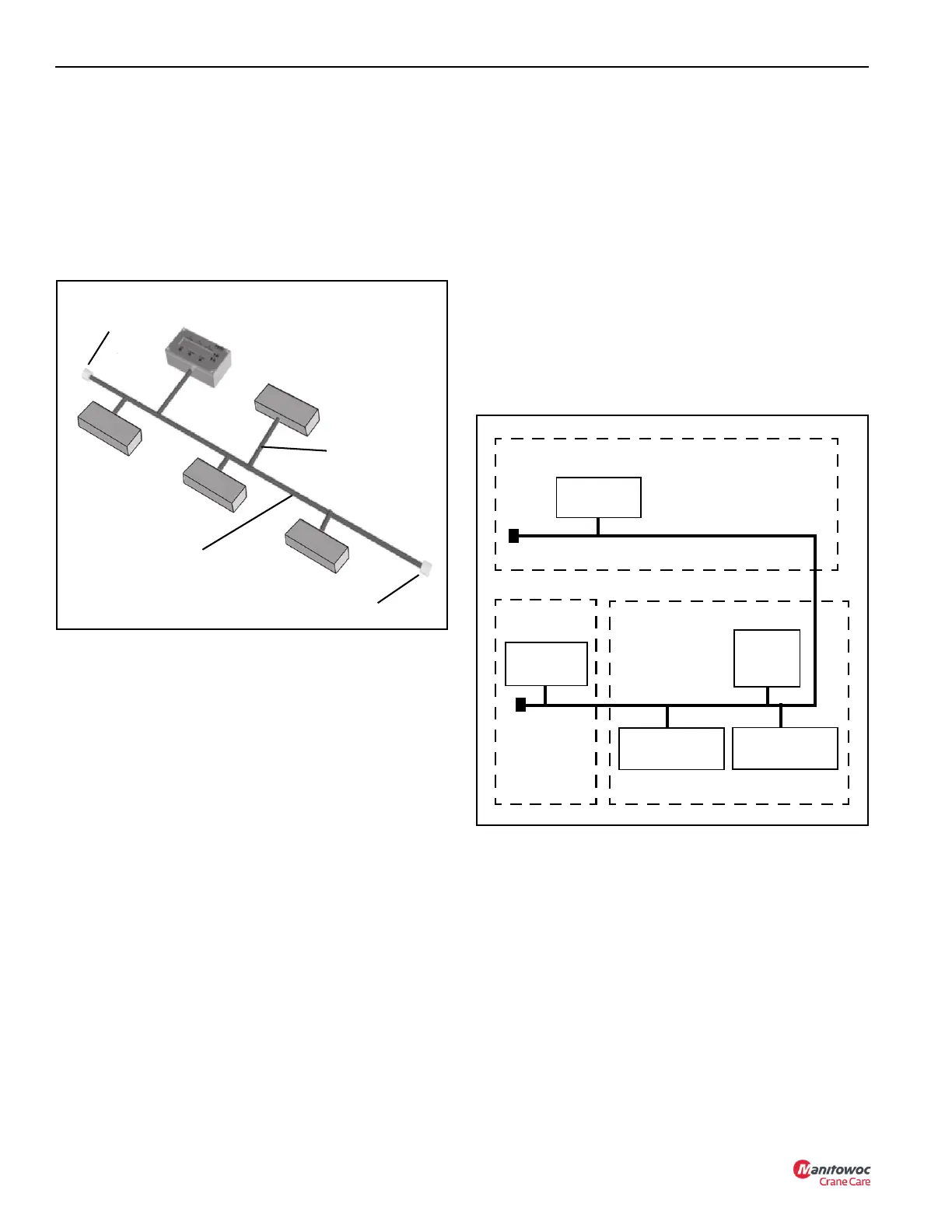
RCL Master
Module
Main CAN Line
40 meter Max
Node Drop Line
1 meter Max
120 ohm
Termination
Resistor
Node
Node
Node
Node
120 ohm Termination
Resistor
RCL Display
Module
Radio Remote
Module (Option)
RCL
Master
Module
RCL
Sensors
Termination
Resistor
Termination
Resistor
Main CAN Line
Under Boom
Control Console
Display Console - Swing Arm
Throttle Module
(Option)

 Loading...


