National Crane 03-20-2019 Control # 613-06 3-3
NBT30H-2 SERVICE MANUAL ELECTRIC SYSTEM
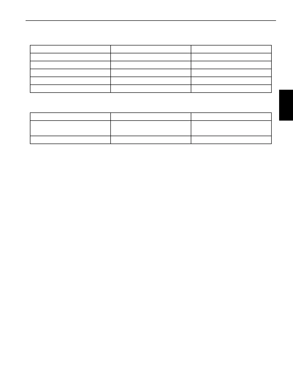
Table 3-2
Deutsch Extraction Tool Table
Table 3-3
Deutsch Crimping Tool Table
Troubleshooting Electrical System
Finding a problem in the electrical system is not difficult if you
know basic electricity and understand the arrangement of
the electrical system. Use your electrical schematic.
Accurate testing equipment is also necessary. The
instruments normally used are a voltmeter, ammeter,
ohmmeter and test light.
Many times the problem can be found by visual inspection of
the components in the circuit. Corrosion on terminals, loose
connections or bad wiring are the causes of many problems.
Each circuit in the system has a fuse for protection against
overloads. Remember that a burnt fuse is an indication of an
overload or SHORT circuit, not an OPEN circuit.
If you did not find the cause of the problem during the visual
inspection, use a voltmeter to check the voltage at several
points in the circuit, or measure voltage drop across the
component. Normally, the best method is to start at the
furthest component in the circuit and move backwards
toward the power supply. An ohmmeter can be used to
measure the resistance in any component.
NOTE: Remember to disconnect the component from the
power supply before you connect the ohmmeter.
Ignition Switch
There are three ignition switches on the crane. A keyed
ignition switch is in the truck cab and two Stop/Run/Start
Switches are located on the operator control console. The
crane system is in series with the truck ignition circuit. All
ignition switches (truck key) switch and both crane console
switches must be in the ON position, set to RUN, before the
truck can be started from either the truck cab or the operator
control console.
The switch has three positions. STOP shuts down engine
and crane power, RUN activates truck engine ignition and
crane power, and START to start the truck engine.
NOTE: The truck cab ignition and both console switches
must be in the ON position, set to RUN, before the
engine can be started using the Stop/Run/Start
Switch.
NOTE: If one switch does not engage the truck starter,
check and make sure the other switches are ON
and there are no active E-stops.
When all crane ignition switches are ON and the PTO
engaged, the throttle pedal in the operator station overrides
the truck cab throttle, the RCL system and the crane
functions are activated.
RCL SYSTEM DESCRIPTION
The Rated Capacity Limiter (RCL) is an operational aid that
monitors crane operation and alerts the operator of
impending dangerous condition that could result in death or
injury to personnel and/or damage to equipment and
property (Figure 3-1).The crane functions that worsen the
overload condition (Boom Down, Telescope Out, Hoist Up
and Swing) are disabled.
A RCL override key switch is located behind an access panel
on the passenger side console. Turn the key switch ON to
override the RCL.
A momentary RCL override switch is located at the center of
the operator control console. The RCL memory always has
Description Deutsch Part Number National Crane Part Number
12 gauge wire 114010 9999100194
16 gauge wire 0411-204-1605 9999100195
8-10 gauge wire 114008 7902000012
4-6 gauge wire 114009 7902000009
20-24 gauge wire 0411-240-2005 9999102084
Description Deutsch Part Number National Crane Part Number
12, 14, 16, 18, 20,
22, 24 gauge wire
HDT-48-00 9999100808
4, 6, 8, 10 gauge wire HDT04-08 9999100842

 Loading...


