CRANE INSTALLATION NBT30H-2 SERVICE MANUAL
9-16 03-20-2019 Control # 613-06
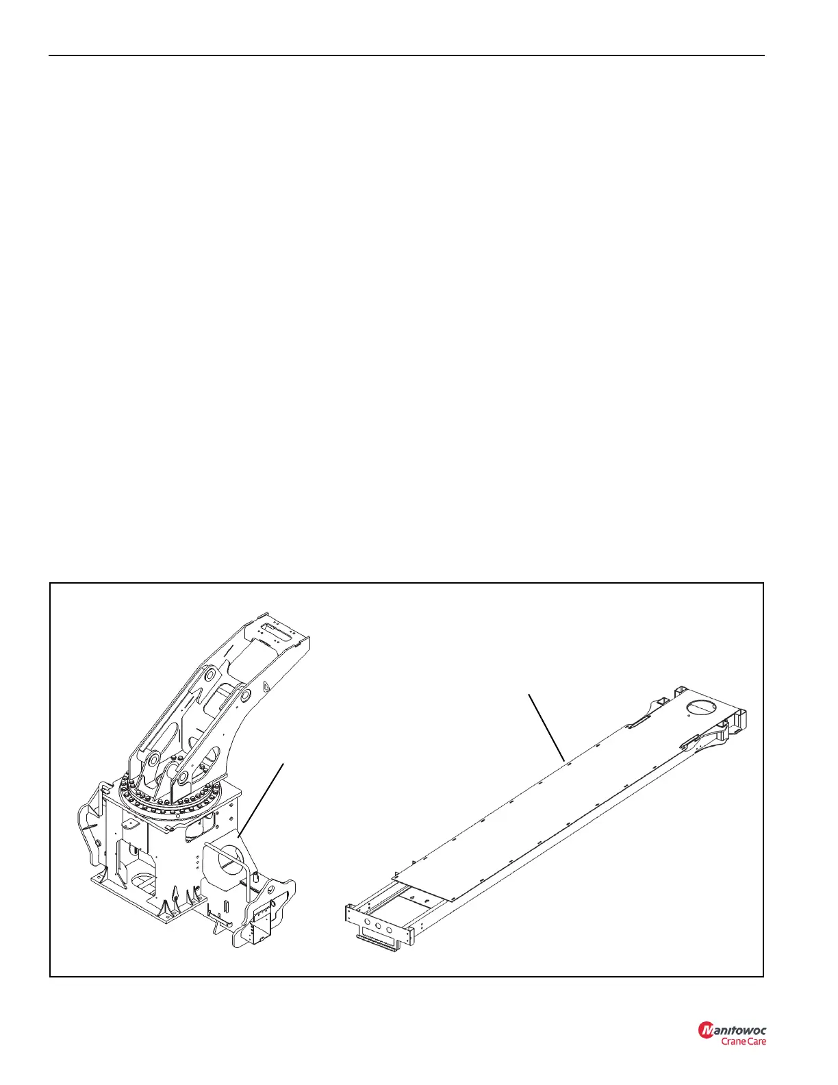
• Mount the torsion box (T-box) on the truck frame (Mount
the T-Box, page 9-16).
• Attach the RSOD to the truck frame and T-box (Attach
the RSOD, page 9-18).
• Mount the frame assembly on the T-box (Mount the
Frame Assembly, page 9-19).
• Install the front outriggers (Install the Front Outriggers,
page 9-19).
• Install the boom rest on the T-box and rear bumper on
the truck frame (Install the Boom Rest, page 9-20).
• Mount the operator stations and install the foot throttles
(Mount the Operator Platforms and Install the Foot
Throttles, page 9-21).
• Install the boom, lift cylinder, and hoist (Install the Boom,
Lift Cylinder, and Hoist, page 9-21).
• Install the RCL reel under the boom (Install the RCL
Reel, page 9-21).
• Connect the slew potentiometer Connect the Slew
Potentiometer, page 9-22.
• Connect the electrical interface (Connect the Electrical
Interface, page 9-22).
• Install the hydraulic system (Install the Hydraulic
System, page 9-23).
• Complete the initial crane run in procedure (CANBUS
System Setup, page 9-26).
• Calibrate the RCL and do the stability test (RCL
Calibration, page 9-26).
Mount the T-Box
1. Position the truck so that the truck frame is level.
2. Place the T-box on the truck frame as determined by the
information contained in the section titled Positioning the
Crane On the Truck, page 9-11.
NOTE: The top and bottom T-box reinforcing plates must
extend past the RSOD mounting position
(Figure 9-12). If this cannot be accomplished
because of a long cab to tandem (CT) dimension,
contact the factory.
3. Clamp the anchor brackets on the truck frame so that
the holes for the anchor bolts line up with the tubes for
the anchor bolts (Figure 9-12). Check for interference
with truck frame crossmembers.
NOTE: If the T-box does not fit tightly against the truck
frame, clamp the T-box and truck frame together to
remove the gaps.
4. Drill four 3/4 inch holes in the truck frame for each crane
anchor bracket.
5. Bolt the anchor brackets to the truck frame as shown in
Figure 9-13. Torque to recommended values in
Fasteners and Torque Values, page 1-12.
Torsion Box (T-Box)
Frame Assembly
FIGURE 9-11
8745

 Loading...


