National Crane 03-20-2019 Control # 613-06 3-9
NBT30H-2 SERVICE MANUAL ELECTRIC SYSTEM
Rear Outrigger Manifold
The solenoids on the rear outrigger manifold control the rear
outrigger components. See Figure 3-7 for solenoid
identification.
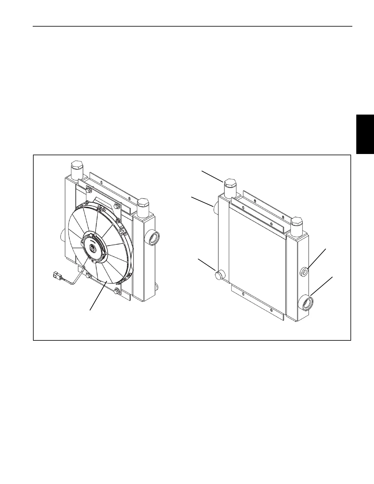
HYDRAULIC OIL COOLER OPTION
The optional hydraulic oil cooler (Figure 3-8) is mounted in
front of the frame. An electric fan in the crane frame,
circulates air over the cooling core when the hydraulic oil in
the cooling core reaches 48.8° C (120° F).
Not all return flow is routed through the oil cooler. A 206 kPa
(35 psi) check valve in the oil cooler limits the flow through
the cooler. Since hydraulic oil is thicker when it is cold, less
oil is routed through the cooler when it is cold than when it is
hot.
The cooler electrical system is made up of the following:
• Electric Fan
• Fan Relay
• Temperature Sensor
The temperature sensor is located in the cooling core and
energizes the fan relay when the hydraulic oil reaches 48.8°
C (120° F). The fan relay (R3) is located in the micro relay/
fuse box and turns the fan on when energized (Figure 3-4). If
the fan is not running and the oil temperature warning is
displayed on the RCL screen, check the fan temperature
sensor, relay, and fan motor.
FIGURE 3-8
Plug
OIl Cooler Fan
Inlet
Outlet
Temperature
Sensor
Bypass
Valve

 Loading...


