ELECTRIC SYSTEM NBT30H-2 SERVICE MANUAL
3-8 03-20-2019 Control # 613-06
.
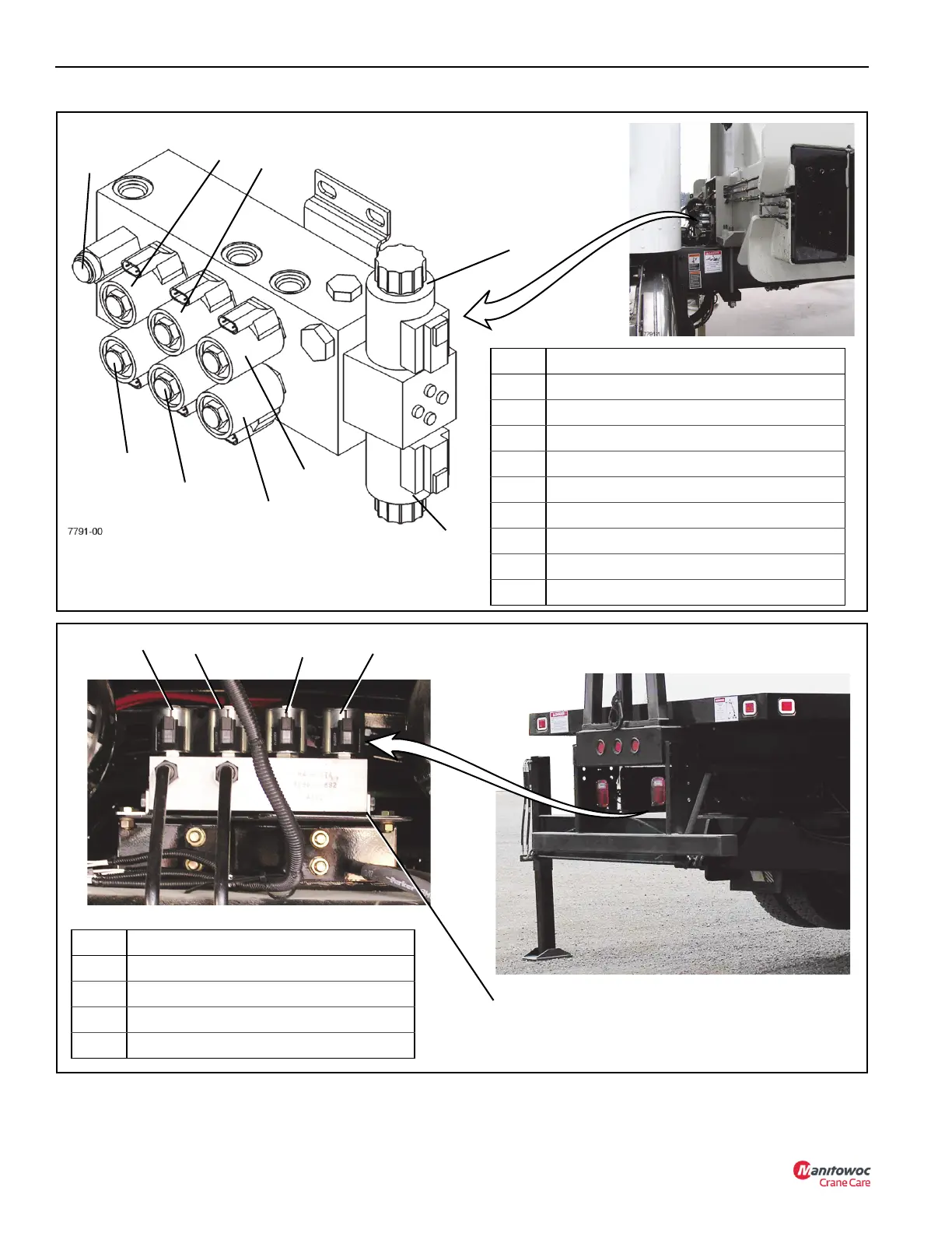
FIGURE 3-6
Item Solenoid
1 Beam Extend Relief Valve
2 Beam Extend Relief Solenoid
3 Driver Side (Left) Beam
4 Center Front Jack (SFO) (Optional)
5 Passenger Side (Right) Jack
6 Passenger Side (Right) Beam
7 Driver Side (Left) Jack
8 Extend
9 Retract
3
2
6
7
5
4
9
Front Outrigger Manifold
8
1
Item Solenoid
1 Driver Side (Left) Outrigger
2 Driver Side (Left) Beam
3 Passenger Side (Right) Beam
4 Passenger Side (Right) Outrigger
FIGURE 3-7
1
2
3
4
Rear Outrigger Manifold
(Viewed from Rear of Vehicle)

 Loading...


