HYDRAULIC SYSTEM NBT30H-2 SERVICE MANUAL
2-12 03-20-2019 Control # 613-06
VALVES
General
This subsection provides descriptive information for all the
hydraulic valves used on this crane. For a listing of all valves,
the circuit they are used in, and their physical location, refer
to the table on page 2-12. The description of each valve
given here is for the valve itself. For information on how each
valve functions in the individual circuits, refer to the
description and operation procedures of that circuit.
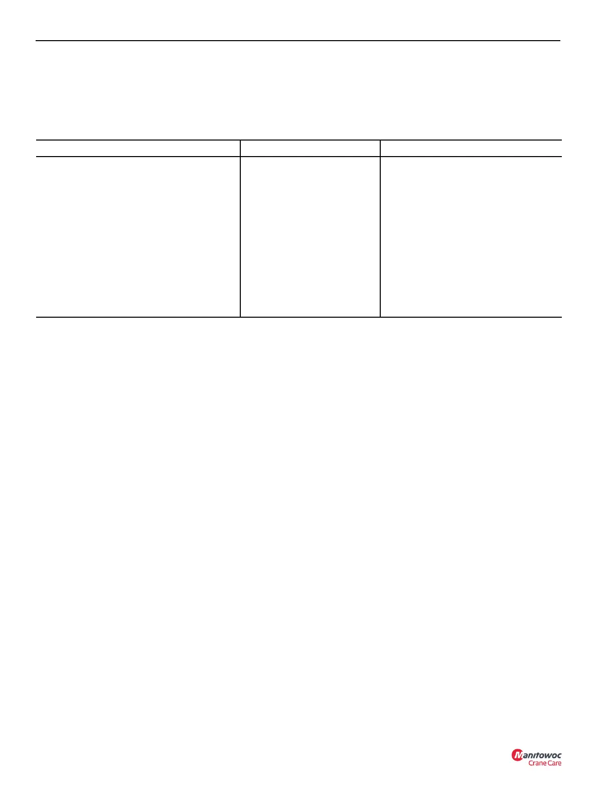
Valve Name Circuit Used In Physical Location
Directional Control Valve Boom Lift, Telescope, and Swing Mounted inside operator console.
Holding Valves
Boom Lift, Telescope, Hoist and
Outriggers
Port block on cylinder
Hoist Motor Counter Balance Valve Hoist On hoist motor
Front Outrigger Selector and Control Manifold Outrigger Manifold on front outrigger box.
RSOD Control Manifold Outrigger Manifold above rear outrigger box.
Pilot Operated Check valve Outriggers Port block of each outrigger cylinder (4)
Swing Counterbalance and Speed Flow Valves Swing On swing motor
High Speed Hoist Control Solenoid Hoist On hoist motor
Front center outrigger relief valve Outrigger On SFO

 Loading...


