National Crane 03-20-2019 Control # 613-06 9-7
NBT30H-2 SERVICE MANUAL CRANE INSTALLATION
TRUCK FRAME STRENGTH
For a truck frame to be suitable for a Series NBT30H-2
crane, the truck frame must:
• be rigid enough to prevent excessive boom movement
due to truck frame deflection when lifting over the front of
the unit.
• be strong enough to resist the loading induced by the
crane.
• not permanently bend or deform.
The Section Modulus (S.M.), which determines the rigidity of
the frame, is a measurement of the area of the truck frame.
Resistance to bending moment (RBM) is a measurement of
strength and is determined by multiplying the section
modulus of each frame rail by the yield strength of the rail
material.
The NBT30H-2 Series require a minimum of 372,850 N·m
(3,300,000 in-lb) RBM and 492 cm
3
(30 in
3
) S.M. from the
rear of the truck frame to the front of the front outrigger
boxes. The truck frame strength required from the front of the
outrigger boxes to the front stabilizer attachment point is
variable and is listed in the table below. Most truck frames
have reduced section properties through the front
suspension due to truck frame cut outs or because outer
channel reinforcement stops short of the front suspension. In
these cases it is imperative that the truck frame is measured
and the section modulus is calculated and compared to the
table below to ensure adequate strength exists for front
stabilizer loading.
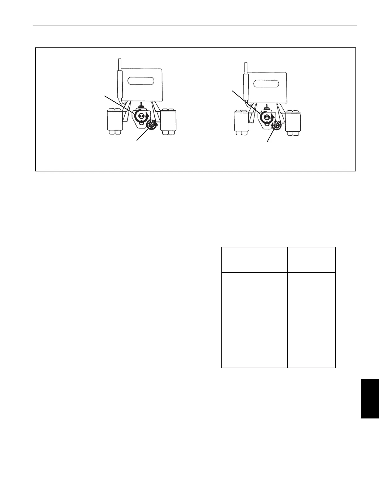
Engine CCW
PTO CCW
Engine CCW
PTO CW
View from Rear of Truck
FIGURE 9-5
Distance From
Stabilizer Attachment
centimeters (Inches)
Section
Modulus Per
Rail cm
3
(in
3
)
0 - 30 (0 - 12) 44 (2.7)
30 - 61 (12 - 24) 90 (5.5)
61 - 91 (24 - 36) 134 (8.2)
91 - 121 (36 - 48) 180 (11.0)
121 - 152 (48 - 60) 224 (13.7)
152 - 182 (60 - 72) 270 (16.5)
182 - 213 (72 - 84) 315 (19.2)
213 - 243 (84 - 96) 359 (21.9)
243 - 274 (96 - 108) 405 (24.7)
274 - 304 (108 - 120) 449 (27.4)
304 + (120+) 492 (30.0)

 Loading...


