National Crane 03-20-2019 Control # 613-06 9-5
NBT30H-2 SERVICE MANUAL CRANE INSTALLATION
MOUNTING CONFIGURATION
The mounting configuration shown in Figure 9-2 is based on
an 85% stability factor. The crane must be installed on the
truck in accordance with factory requirements and a test
performed to determine the stability and counterweight
requirements. If the bare truck weights are not met, a
counterweight is required. A summary of mounting and truck
requirements are:
• Working area - 360° (SFO Required)
• Working area - Limited to 180° with no SFO.
• Gross Axle Weight Rating (GAWR) front - 8165 kg
(18,000 Ib)
• Gross Axle Weight Rating (GAWR) rear - 15455 kg
(34,000 Ib)
• Gross Vehicle Weight Rating - 23587 kg (52,000 Ib)
NOTE: Gross Vehicle Weight Rating (GVWR) is
dependent on all components of the vehicle (axles,
tires, springs, frame, etc.) meeting manufacturer’s
recommendation. Always specify GVWR when
purchasing trucks.
• Wheelbase (WB) - 6.50 m (256 in)
• Cab to Axle Trunnion (CT) - 4.88 m (192 in)
• After Frame (AF) - 2.67m (105 in)
• For 180° working area – Frame Section Modulus (SM)
from outrigger to RSOD -327 cm
3
(20 in
3
)
and 759 MPa
(110,000 psi) material (See Truck Frame Strength
section).
• For 360° working area – Frame Section Modulus (SM)
from front spring hanger to end of after frame – 492 cm
3
(30 in
3
) and 759 MPa (110,000 psi) material (See Truck
Frame Strength section).
• The estimated bare chassis weights and CG required for
stability prior to installation of crane or accessories are:
- 8619 kg (19000 Ib) with a minimum moment of
345,637 cm-kg (300000 in-lb) about centerline of
rotation.
Tractor Mounting Configuration
• Wheelbase (WB) - 6.50 m (264 in)
• Cab to Axle Trunnion (CT) - 2.33 m (92 in)
• After Frame (AF) - 2.13 m (84 in)
• Gross Axle Weight Rating (GAWR) rear - 20865 kg
(46,000 Ib)
PTO AND HYDRAULIC PUMP
Horsepower
An axial piston pump is furnished with this crane. The pump
uses a load sense system to supply flow to the crane
hydraulics. With load sense, only the systems that are
working are supplied with flow. To provide these flows, the
pump shaft must turn at 2400 RPM. The PTO requirement is
210 HP (156.5 kW).
Direct PTO Mount
In most installations the pump can be mounted directly to the
PTO using adapter assemblies available from the PTO
supplier. If the pump is direct mounted, its weight should be
supported by a strap between the pump and the
transmission. The splined shaft coupling in a direct mount
pump installation requires lubrication. #200S Silver Streak
Special Multi-Lube (Medium) is applied to the shaft during
original installation and reapplied to the shaft or grease fitting
provided on PTO housing shaft semi-annually thereafter.
PTO Ratio
Pump shaft speed is determined by truck engine RPM and
PTO ratio:
Pump Shaft Speed = Truck Engine RPM x PTO Ratio
The following PTO ratio and engine speed combinations
provide proper pump shaft speed which is the recommended
maximum speed for the NBT30H-2 pump.
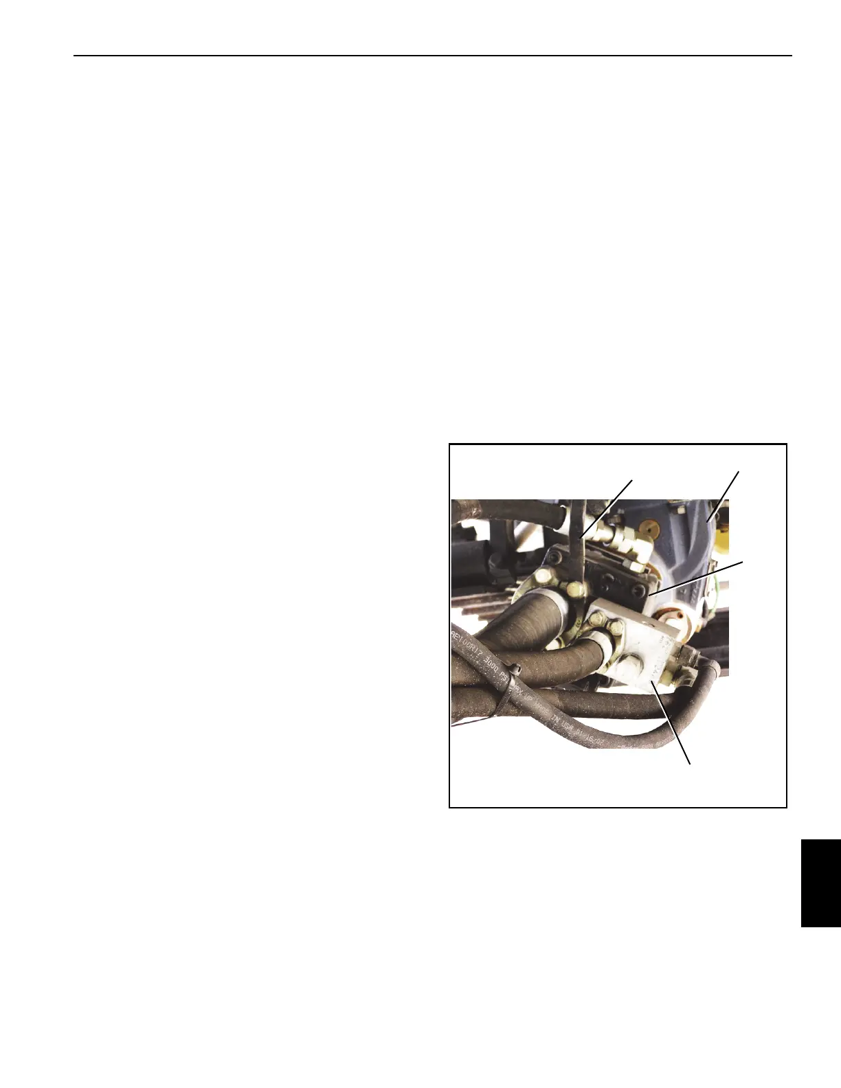
FIGURE 9-3
Mounting
Strap
Pump
PTO
Pump
Manifold

 Loading...


