National Crane 03-20-2019 Control # 613-06 3-21
NBT30H-2 SERVICE MANUAL ELECTRIC SYSTEM
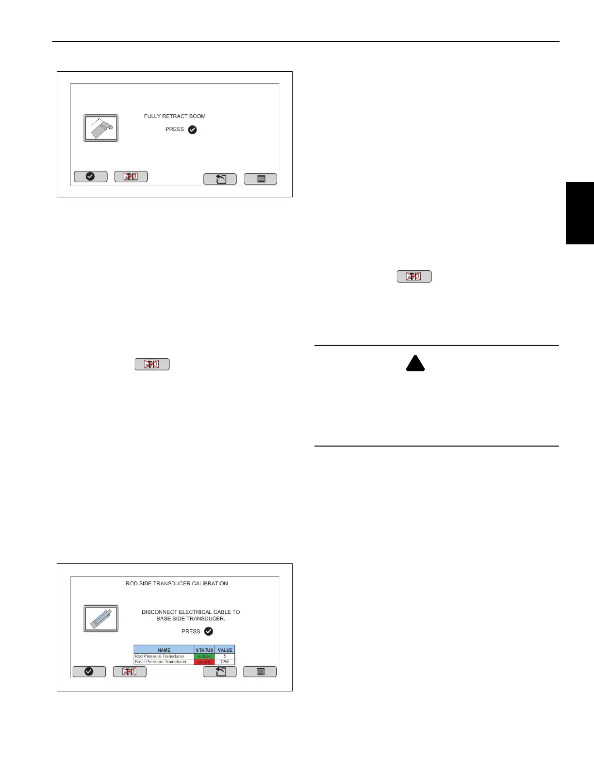
Boom Length Sensor Calibration
Two calibration positions are shown one at a time starting
with the fully retracted position on the Boom Length
Calibration screen.
Once the boom is positioned and confirmed, the next
calibration position will be activated.
- Fully retract the boom.
- Press the checkmark to confirm.
- Fully extend the boom.
- Press the checkmark to confirm.
Pressing Button #2 will reset the calibrated values
for boom length sensor.
Rod Side Pressure Sensor Calibration
The lift cylinder rod side transducer must be assigned with
the correct node ID before the crane is used to lift any load.
Use the following instructions and screen to calibrate.
Level and set the truck on outriggers before starting the
pressure sensor calibration procedure.
Lower the boom until the lift cylinder is fully retracted.
Select the rod side transducer icon from the Rod Side
Pressure Sensor Calibration menu screen (Figure 3-16) to
start the lift cylinder rod side pressure sensor transducer
calibration.
Rod Side Pressure Sensor Calibration
Two calibration steps are shown one at a time on the Rod
Side Pressure Sensor Calibration screen. Once a step has
been confirmed, the next step will be displayed. Follow
instructions on display to reprogram the rod side pressure
transducer.
- Disconnect the electrical cable to base/piston side
transducer to temporarily remove it from the
CANBUS.
- Press the checkmark to confirm.
- Reconnect the electrical cable to base/piston side
transducer.
- Press checkmark to confirm.
- Save the new Node ID by cycling the power to the
rod side sensor using the ignition switch or by
manually disconnecting/reconnecting.
Pressing Button #2 will reset the calibrated values
for rod side pressure Sensor.
NOTE: If rod side transducer is not connected, the icon will
have a Red background.
Base Side Pressure Sensor Calibration
The lift cylinder base side transducer must be assigned with
the correct node ID before the crane is used to lift any load.
Use the following instructions and screen to calibrate.
- Level and set the truck on outriggers before starting
the pressure sensor calibration procedure.
- Lower the boom until the lift cylinder is fully
retracted.
Select the base/piston side transducer icon from the Base
Side Pressure Sensor Calibration menu screen
(Figure 3-17) to start the lift cylinder base/piston side
pressure sensor calibration.
CAUTION
For this procedure it is only necessary to disconnect the
pressure transducers electrically. If you do disconnect the
pressure transducers hydraulically, make sure there is no
hydraulic pressure in the hydraulic line when
disconnecting the pressure transducers. Pressurized
hydraulic fluid can cause personal injury.

 Loading...


