National Crane 03-20-2019 Control # 613-06 2-19
NBT30H-2 SERVICE MANUAL HYDRAULIC SYSTEM
SUPPLY CIRCUIT
Description
The supply pressure and return circuit routes hydraulic oil
from the hydraulic pump to the directional control valve for
the individual operating circuits. The supply and return circuit
consists of the reservoir and spin-on filter, hydraulic pump,
and optional hydraulic oil cooler.
Hydraulic Reservoir and Filter
The reservoir, (Figure 2-11) is attached to the left side of the
truck underneath the bed and has a capacity of 276.3 liters
(73 U.S. gallons) to the full mark. The all-steel reservoir has
two spin-on full flow filter mounted on the front of the tank.
Internal baffles help cool the hydraulic oil and prevent
foaming.
Hydraulic oil flows through the suction line at the lower rear
of the reservoir to the hydraulic pump. Most of the return flow
goes through the spin-on filter at the front of the reservoir.
Return lines (10,11,12,13 Figure 2-11) go directly into the
reservoir instead of through the filter.
A magnetized drain plug in the bottom of the reservoir
collects metal particles from the hydraulic oil if it becomes
contaminated.
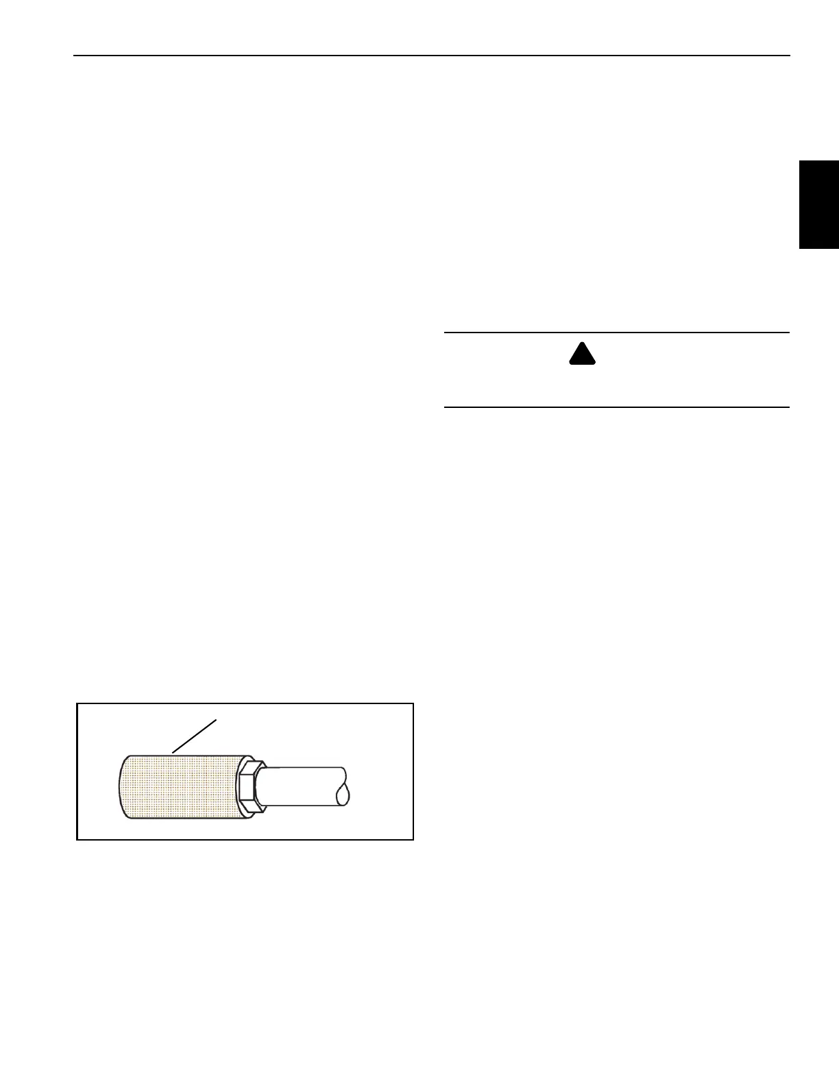
A 100 mesh screen inlet strainer (Figure 2-12) is located in
the hydraulic tank to help protect the pump from
contamination.
A filler cap on the top of the reservoir is for filling the
reservoir. The filler cap includes a strainer for catching
contaminants and gaskets to prevent leaking. The breather
(vent) allows air to enter or leave the reservoir. The breather
must be kept clean to prevent damage to the reservoir.
A sight gauge is located on the side of the reservoir to
indicate hydraulic oil level.
A large access cover on the top of the reservoir provides
access for cleaning. The cover is secured to the top of the
reservoir with screws and has a gasket to prevent leaking.
The access hole can also be used to fill the reservoir after it
has been completely drained.
The dual spin-on hydraulic oil filters (Figure 2-11) are located
on the front of the reservoir and are replaceable.
Hydraulic Filter Replacement
The filters must be serviced with National Crane
replacement elements at recommended intervals to assure
the warranty remains in effect.
Element Removal
1. Shut down the hydraulic system.
2. Wipe any dirt from the filter head.
3. Place a container underneath the filters to catch spilled
oil, unscrew and remove each filter.
4. Install the new filters.
5. Properly discard the used filters.
Hydraulic Oil Cooler (Option)
An optional hydraulic oil cooler can be installed at the rear of
the frame (Figure 2-13). The oil cooler return circuit is in
parallel with the reservoir return circuit and a 206 kPa (30
psi) integral check valve regulates flow through the oil cooler.
When the hydraulic oil is cold, most of the return oil goes
directly to the tank. As the oil warms up and becomes
thinner, more oil goes through the cooler.
The oil cooler is energized by R3 relay and is in line with fuse
F5. The relay and fuse are located in the micro fuse box in
the crane frame. A temperature switch located in the cooling
core energizes the fan relay when the oil temperature
reaches 48.8 °C (120°F).
100 Mesh Screen
Inlet Strainer
FIGURE 2-12
WARNING
Ensure that hydraulic system is shut down and the
pressure is relieved or personnel injury could result.

 Loading...


