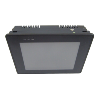
3. From the Edit menu, click Layer, then PreviousLayer or click the PreviousLayer icon from
the Manager toolbar. Note that the rectangle covers the circle but not the arc.
4. From the Edit menu, click Layer, then NextLayer or click the NextLayer icon from the
Manager toolbar. Note that the rectangle recedes behind the circle and the arc.
Normally, an object that is controlled by a PLC Register (i.e., a Word Lamp, Bit Lamp, Animation, etc.) is brought
to the Top Layer when the value in the PLC Register changes. This behavior can be changed by the Part Layout
option on the Editor tab of the System Parameters dialog. A setting of Control is the default, and sets the behavior
as outlined above. A setting of Nature will result in the object remaining at the layer assigned during development.
The Part Layout setting is global, and affects all PLC-controlled objects in the application.
Nudg ing Ob jects
Nudging is used to fine-tune the movement of objects in the work area of EasyBuilder. Using the nudge feature on
a selected object will move that object in the specified direction either by one pixel or by the grid setting amount.
4Using the nudge top , bottom , left , and right commands
1. Select one of the layered objects or a group of objects in the work area of EasyBuilder.
2. From the Edit menu, click Nudge, then select the direction of the nudge or click the
appropriate icon from the Manager toolbar.
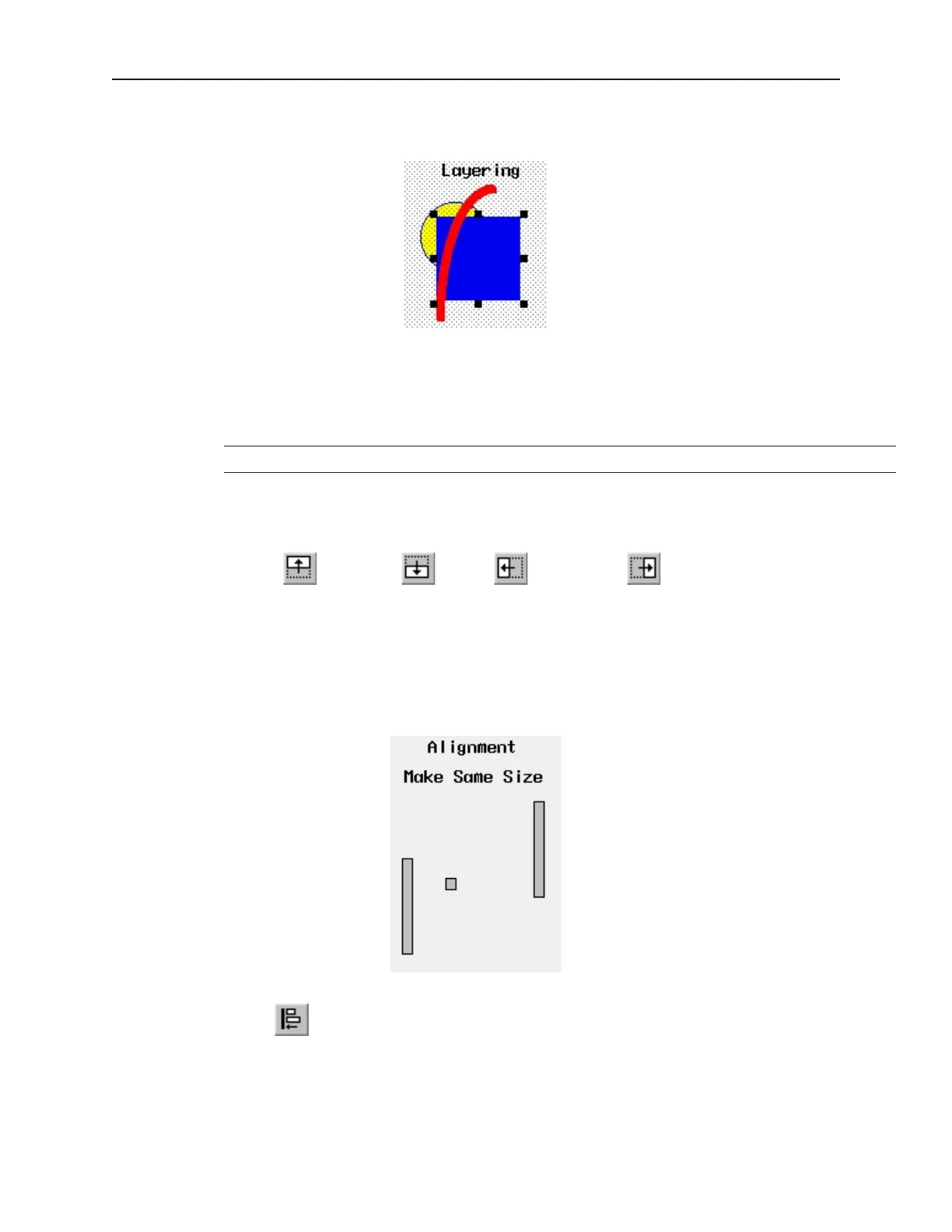
Aligning Ob jects
Alignment can be used to quickly align two or more objects. To better illustrate, refer to the left side of Window_12
of the sample project:
4Using the align left command
1. Select the objects you wish to align. For this example, select the three rectangle objects of
Window_12
1010-1001a, Rev 02
Using EZware-500 51