Do you have a question about the MASSO G3 and is the answer not in the manual?
Guide for new users to set up key configuration properties in MASSO.
Details the steps for opening the enclosure and installing the E-Stop button.
Explains the power supply requirements and connection for MASSO-G3.
Provides instructions for loading software onto the MASSO-G3 unit.
Details the software loading process for the MASSO-G2 controller.
Explains default passwords and how to change or remove them.
Covers wiring axis and spindle drives to MASSO, followed by calibration.
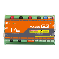
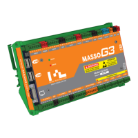
Provides a general overview of what MASSO is and its capabilities.
Discusses compatibility and wiring of stepper and servo motors with MASSO.
Information on using MASSO with plasma machines, including THC support.
Information on MASSO's built-in logic for various tool changers.
Describes the different screens and elements of the MASSO graphical interface.
Lists essential keyboard shortcuts for navigating MASSO interface and functions.
Instructions on loading and running G-code files from a USB drive.
Procedures for calibrating tools for both lathe and mill operations.
Details on using conversational wizards for basic machining programs.
Explains the G00 command for rapid movement to a specified location.
Explains the G01 command for linear movement at a specified feedrate.
Command used for probing parts or fixtures to find the workpiece top.
Commands to select the current work offset for use in machining.
Sets the distance mode to absolute, which is the default on power up.
Command to stop the program, resumed by pressing cycle start.
Starts the spindle rotation in a clockwise direction at specified RPM.
Command to stop the spindle rotation.
Command used to change the tool immediately with T value.
Supports sub-program calls using M98 & M99 codes for reusable code blocks.
Provides mechanical dimensions for MASSO G3 Touch and MASSO G3.
Details wiring examples for single and multiple E-Stop buttons.
Explains wiring precautions for axis Step and Direction signals.
Steps for calibrating axes after electrical connections are made.
Details on mounting and assigning inputs for homing sensors.
Explanation of soft and hard limits for axis travel prevention.
Describes wiring for A & B axes on MASSO G2 and refers to G3 for X, Y, Z.
Information on various tool changers for milling machines.
Information on various tool changers for lathe machines.
Wiring and control signals for the Proma Compact THC 150.
Using the torch touch signal for floating head gap calibration.
Overview of THC interface, G-code commands, and operation principles.
| Storage | 8GB eMMC |
|---|---|
| Connectivity | Ethernet, USB |
| Power Supply | 24V DC |
| Isolated Inputs | 16 |
| Isolated Outputs | 8 |
| Relay Outputs | 2 |
| Encoder Inputs | 4 |
| Step/Direction Outputs | 6 |
| Analog Inputs | 2 |
| Digital Inputs | 16 |
| Digital Outputs | 8 |
| Humidity | 10% to 90% non-condensing |
| Display | 7-inch touchscreen |
| Axes | Up to 6 axes |
| Spindle Control | PWM, Analog, or Step/Direction |
| Software | MASSO OS |
| Operating Temperature | 0°C to 50°C |
| Storage Temperature | -20°C to 70°C |
| Memory | 1GB RAM |
| Output Current | 500 mA per output |