M
Mr. Ian SwansonAug 21, 2025
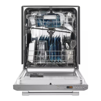
Why is my Maytag MDB Dishwasher so noisy?
- MMichael HahnAug 21, 2025
A noisy Maytag dishwasher can be caused by several factors. The spray arm might be stalled or blocked, spraying water directly onto the door; make sure nothing is obstructing the arm's rotation and that the nozzles are clear. If the dishwasher has a fan, excessive noise could be due to a faulty fan; inspect the fan during the service diagnostics test cycle and replace it if it doesn't spin freely. Also, refer to the service error codes table for other possible causes related to water or drain issues.