Page 181 of 188
User Manual MAS-100 Regulus en.docx, Version: 4.0
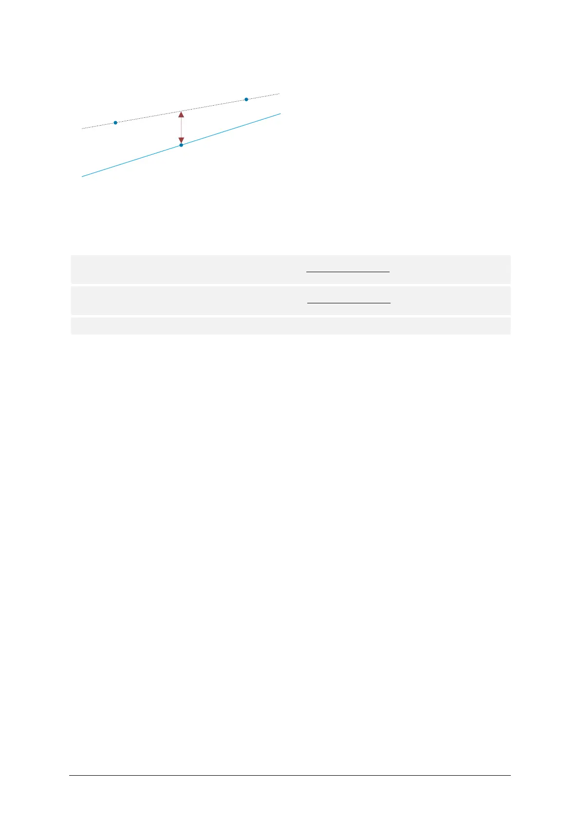
A.2.4 Manual 3-point flow sensor adjustment
The three Adjustment Points are taken. Both parameters, offset and gain are changed.
The Adjustment Points are calculated from the desired Target Flow and the Adjustment
Span as follows:
Adjustment Point □ (Lower) = Target Flow -
Adjustment Span
Adjustment Point □ (Upper) = Target Flow +
Adjustment Span
2
Adjustment Point
(Middle) = Target Flow
Numeric example
With: Target Flow = 100 SLPM
Adjustment Span = 10 SLPM
The three adjustment points will be:
Adjustment Point (Lower) = 100 – 5 = 95 SLPM
Adjustment Point (Upper) = 100 + 5 = 105 SLPM
Adjustment Point (Middle) = 100 SLPM
A.2.5 Automatic flow sensor adjustment by PC Software
This procedure always uses the 3-point adjustment method.
A.2.6 Run time check
During the calibration, the air sampler always checks the internal clocks accuracy. There-
fore, a given time lapse of the internal clock will be compared to the processor time.
In addition, by activating the Run time check acoustical function in the PC Software, the air
sampler allows to verify the internal clock independently with external means. Therefore,
the air sampler marks the beginning and the end of a 100-second interval with acoustic sig-
nals. The time between the acoustic signals can be verified with a calibrated stopwatch.