10
uu
uu
ii
ii
ii
ii
Service manual for medifa 6000 mobile operating tables, version 2.0
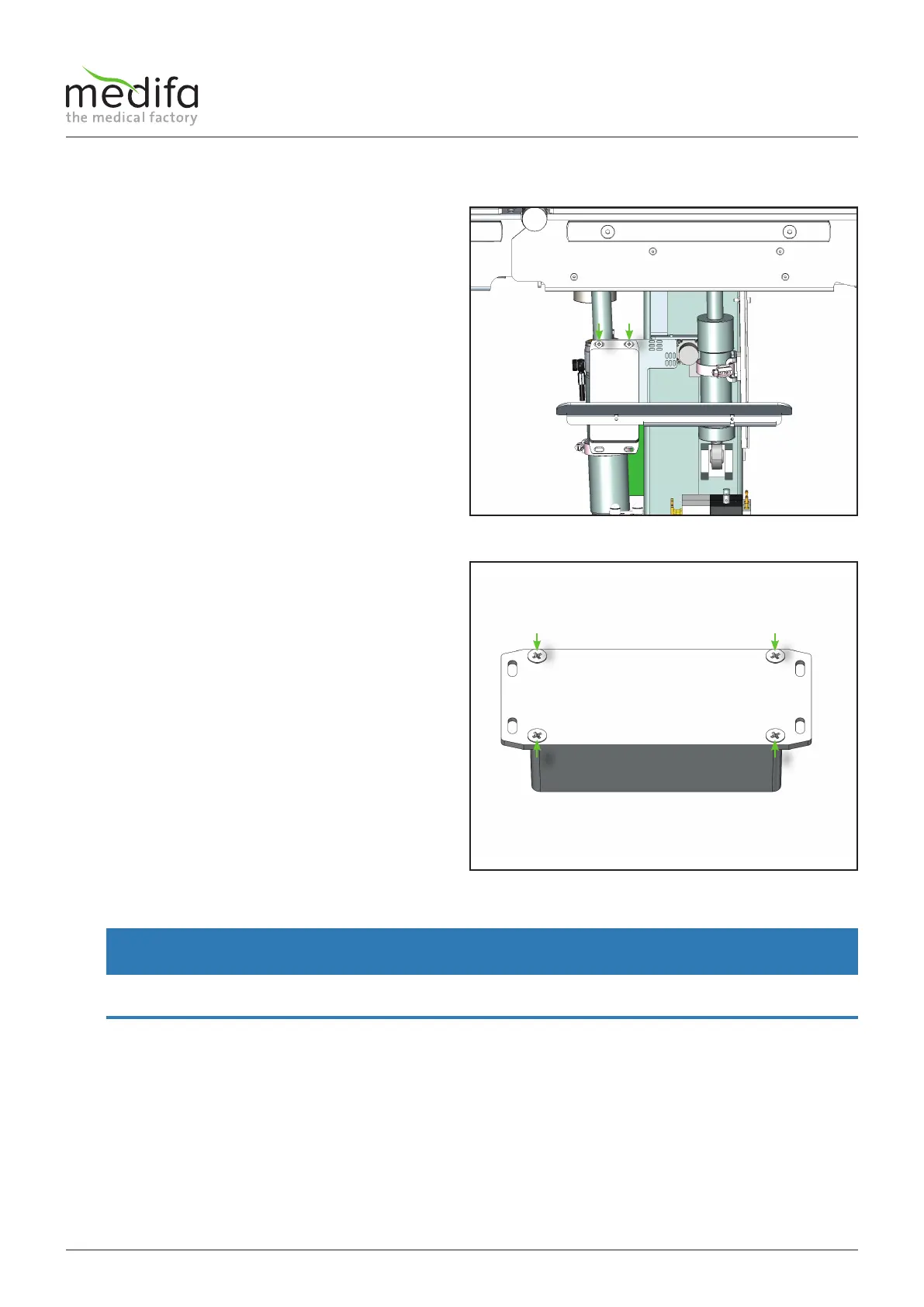
To this end, the supply connection cable must be removed
from the housing and the two screws[7] loosened.
CAUTION: Be careful when dismantling the column
keyboard board, because the ribbon cable of the board
can be damaged by incorrect handling.
Figure 5
Components column / top frame
The next step is to remove the four screws[8] on the back
of the housing of the board.
To do this, turn the housing upside down so that the four
screws marked can be removed from the cover.
WARNING
Do not lift the cover of the housing under extreme force and follow the last step of the repair instructions to avoid damag-
ing the supply interface of the board.
Figure 6