APPENDICES
174
Door
Appendix C – Service Station Guide Installation Instructions
The original Service Station Guide (42-900-25) was designed/developed to help prevent Service Station
misalignment during installation.
NOTE: Starting with S/N 100029449; all printers were shipped with a Service Station Guide pre-installed.
Before You Begin:
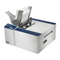
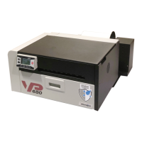
Newer Print Engines (MR) will have a different type of guide
(42-900-26) installed; as shown in the image to the right.
This guide is to be used in conjunction with Rev C Service
Stations. Rev C Service Stations have shortened drive tracks;
allowing them to be inserted further, before the Service
Station engages with the Service Station drive shaft/gears.
NOTE: The Rev C Service Station is also backwards
compatible with the original (old) guide (42-900-25).
If your print engine does not have a Service Station Guide
installed (42-900-25 or 42-900-26), you can choose to install
the new guide (42-900-26 along with a new Service Station (be sure it is Rev C or higher) or you can install
the original guide (42-900-25) with Rev B or lower Service Stations.
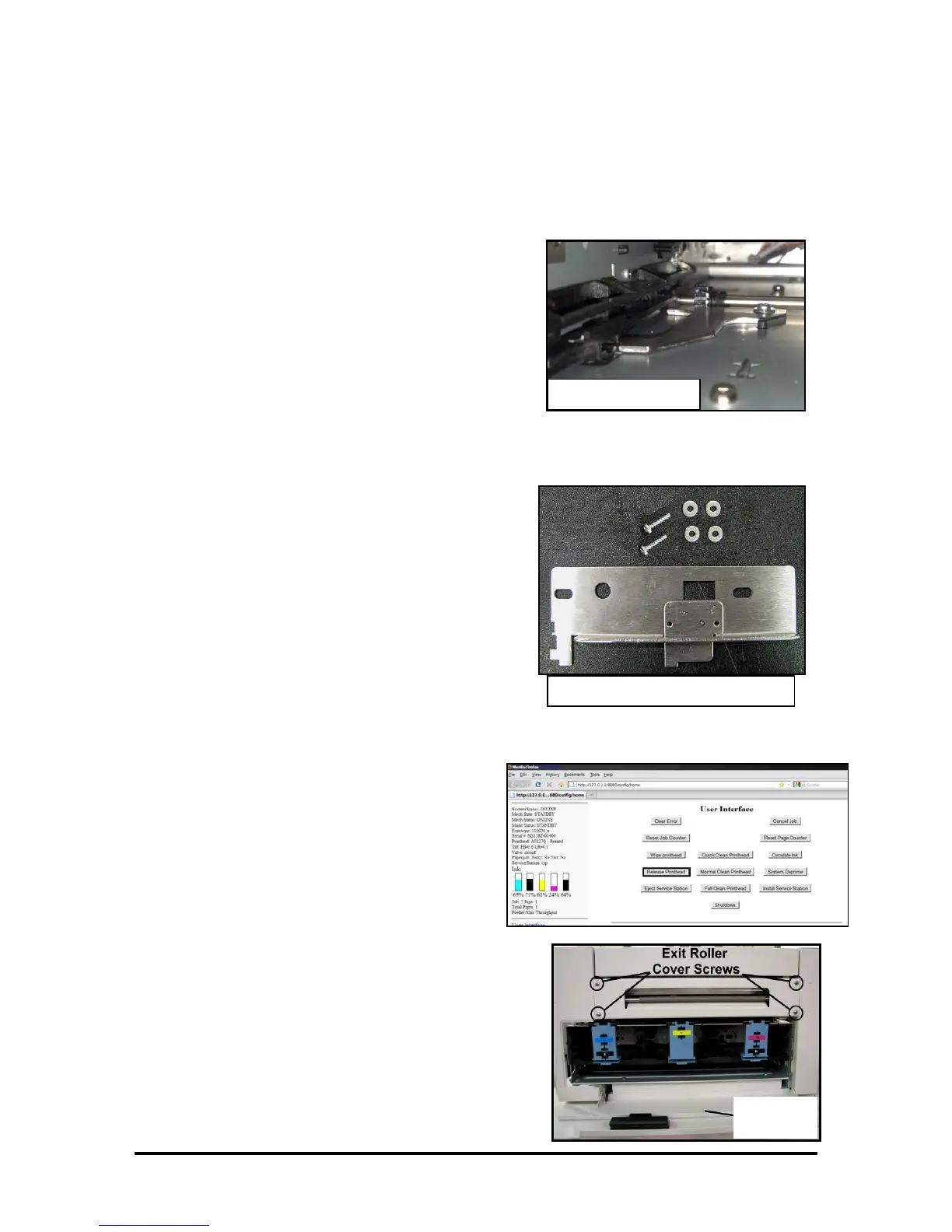
The Service Station Guide Kit (42-900-25) consists of:
(1) Service Station Guide
(2) T10 Torx screws
(4) washers.
Tools/Supplies Needed:
• T10 Torx screwdriver.
• Small Ratchet Wrench (example: Husky SKU 165 152).
• T10 bit (example: DeWalt DW2067) for ratchet wrench.
• Plastic-safe Grease (example: Super Lube
®
21030)
• Small brush to apply grease.
• Rubber gloves
• Towels/Rags
RELEASE AND REMOVE THE PRINTHEAD
1. Make sure the printer is powered-up and
connect to the computer.
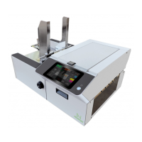
2. Open the M Series Toolbox.
In the User Interface window, press the
Release Printhead button.
The system will do a partial deprime and then
the Printhead Latch will open.
3. Open the Top Cover.
4. Carefully remove the Printhead.
Place the printhead into the orange clip it originally
came in; for safe storage.
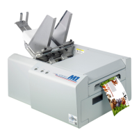
5. Open the Ink Tank Door (hinged at bottom).
6.
Remove the Exit Roller Cover by removing the four
(4) screws.