Construction and Description
13 D53182 02/2024
3.5 Connections and Interfaces
3.5.1 Electrical Connection
This unit is designed for operation on an electrical power system with a maximum system
impedance Z
max
at the point of transfer (service line) of 0.292 Ohm. The operator must
ensure that the unit is only operated on an electrical power system that meets these
requirements.
If necessary, ask your local utility company what the system impedance is. Observe the
country-specific regulations when making connections (e.g. in Germany DIN VDE 0100
with earth leakage circuit breaker).
3.5.2 Communication Interfaces
The communication interfaces are intended for appliances which meet the requirements of
IEC60950-1.
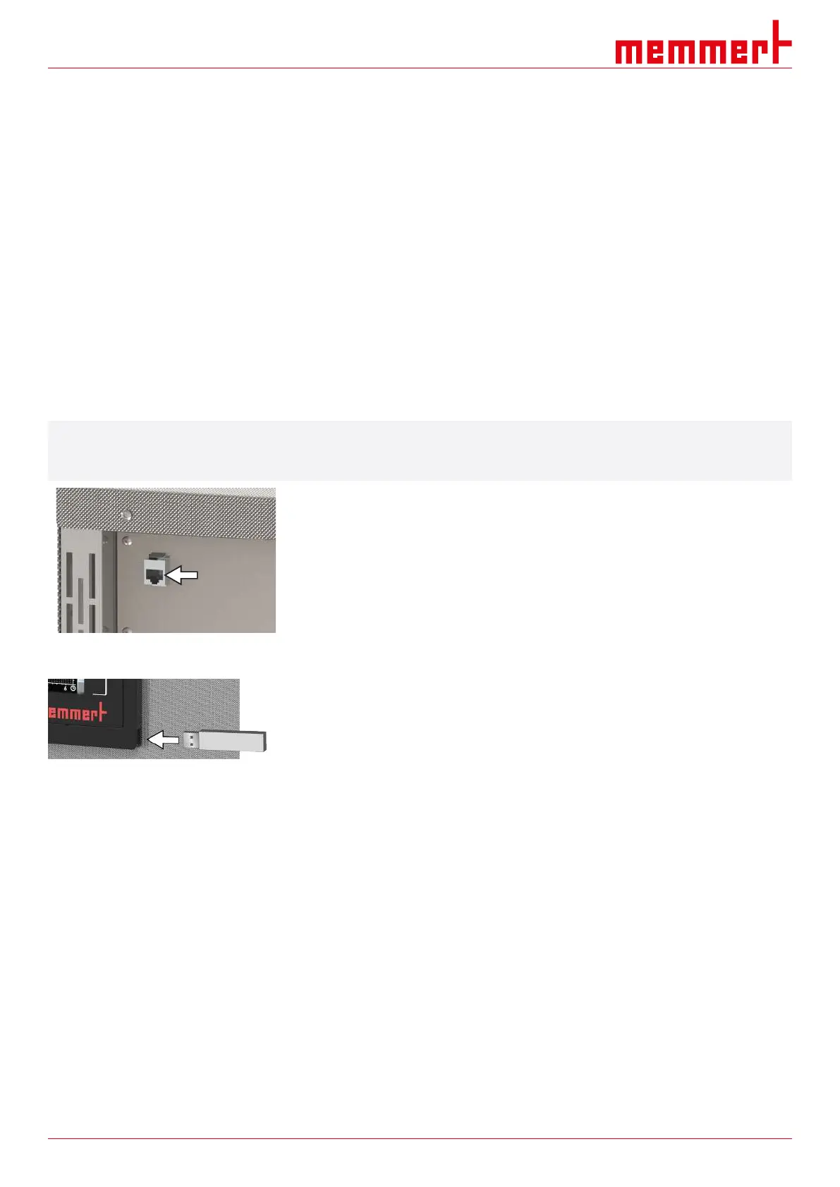
Ethernet interface
i
You will find a description of how to transfer programs via Ethernet in the AtmoCONTROL
software manual.
The unit can be connected to a network via the Ethernet interface, so that you can transfer
programmes created with the AtmoCONTROL software to the unit and export logs.
For identification purposes, each unit connected must have its own unique IP address. A
description of how to set the IP address is provided in chapter }8.3.2 IP Address and
Subnet Mask.
The unit can be directly connected to a computer / laptop using an optional USB to
Ethernet converter (see }3.10Scope of Delivery).
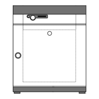
USB interface
The unit comes with a USB port as standard in accordance with the USB specification.
With this you can:
■ transfer software stored on a USB storage medium to the unit
(see }8.6Programme)
■ export logs from the unit to a USB storage medium
(see }8.8Log)
■ transfer user ID data stored on a USB storage medium to the unit
(see }8.9USER ID)
The USB port is located on the right of the ControlCOCKPIT.
See also
2 IP Address and Subnet Mask [}44]
2 Scope of Delivery [}16]
2 Programme [}50]
2 Log [}52]
2 USER ID [}53]
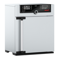
3.6 Nameplate
The nameplate provides information about the appliance model, manufacturer and
technical data. It is attached to the front of the appliance, on the right behind the door
(see }3.1Design).