GASOLINE ENGINES BRAVO MODELS
Page 80 of 116
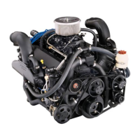
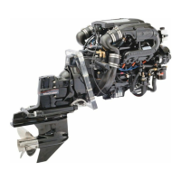
12. Place Remote Control in neutral position.
NOTE: As bell housing shift cable enters the shift linkage assembly, it pushes the assembly
back into the sterndrive housing, and the jaw closes, securing the cable, as shown in steps
“A”, “B” and “C.”
72467
A
C
B
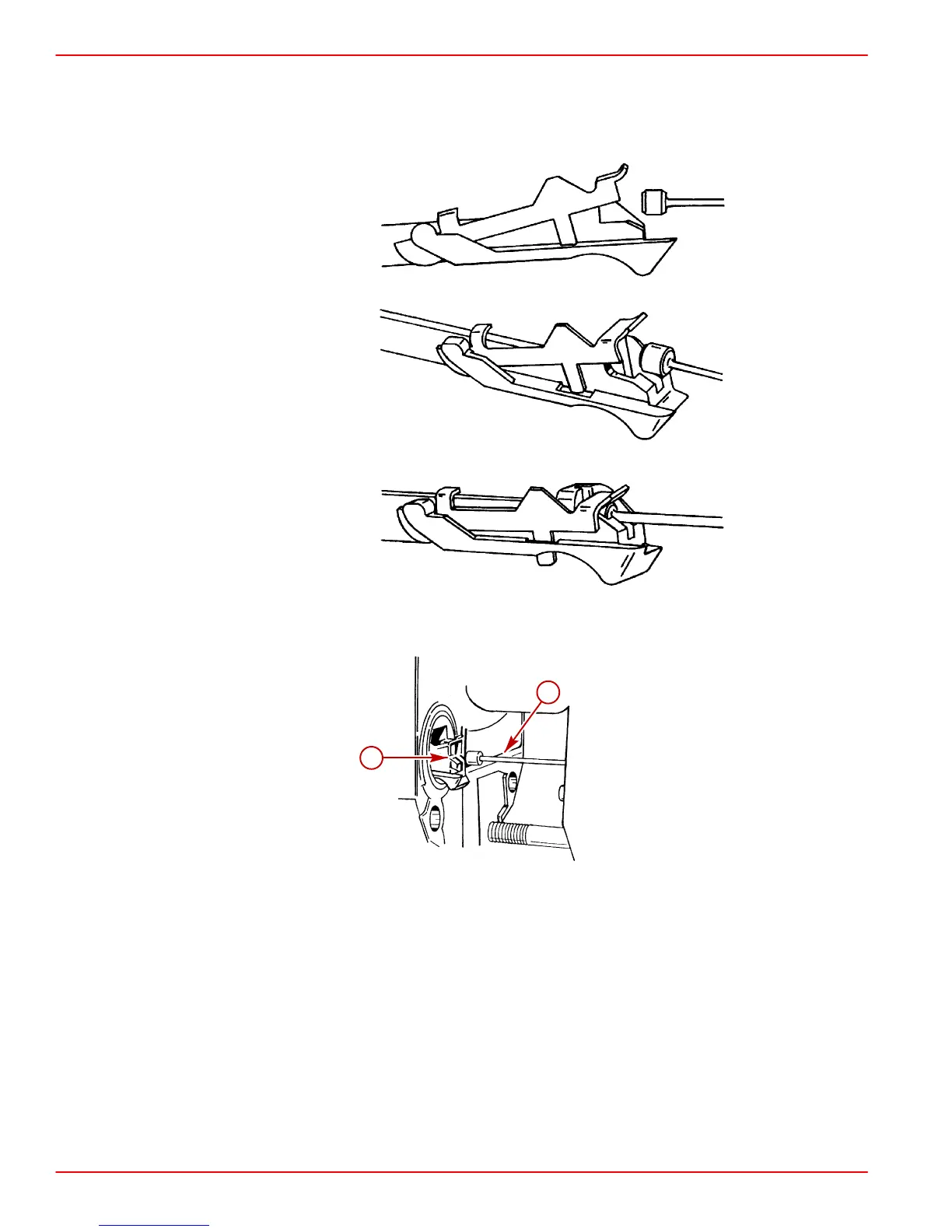
IMPORTANT: If Bell Housing Shift Cable “b” does not line up to properly enter jaws
of shift linkage assembly “a,” cable will have to be aligned manually.
72457
b
a
a-Shift Linkage Assembly
b-Shift Cable
13. Place drive shaft housing in position on bell housing and install sterndrive unit, as fol-
lows:
a. Position trim cylinders so they point straight backwards.
b. Position sterndrive unit so that universal joint shaft aligns with bell housing bore.
c. Guide U-joint shaft through bearing in gimbal housing and into engine coupler. Make
sure that shift linkage jaws engage the bell housing shift cable assembly.
d. If necessary, rotate propeller shaft counterclockwise slightly (using a propeller) to
align U-joint shaft splines with splines in engine coupling, then slide sterndrive unit
all the way into bell housing.