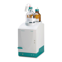
3.6 Installations on the rear of the instrument
■■■■■■■■■■■■■■■■■■■■■■
18
■■■■■■■■
883 Basic IC plus
3
Cable feed-through
For feeding through the detector cable.
4
Detector socket
For connecting the conductivity detector
(see chapter 3.15, page 43). Labeled
Detector.
5
Capillary feed-throughs
For feeding through the capillaries out of the
detector chamber.
CAUTION
The instrument must be switched off when connecting a detector.
1
Checking whether the instrument is switched off
■ If not, switch off the instrument.
2
Removing the back panel
■ Unscrew the knurled screws (4-1) on the back panel.
■ Remove the back panel (4-2).
3
Positioning the detector
■ Position the detector on the support surface intended for this pur-
pose and slide it right up to the front.
4
Replacing the back panel
■ Insert the detector cable in the cable feed-through (4-3) on the
back panel (4-2).
■ Replace the back panel (4-2) and tighten the knurled screws
(4-1).
5
Connecting the detector
■ Connect the detector cable to the detector socket (4-4).
3.6.2 Transport locking screws
To avoid damage to the high-pressure pump drive during transport, the
pump is secured with transport locking screws. These are located at the
rear of the instrument and labeled with Transport security screws
(2-5).
Remove these transport locking screws before the initial start-up.
Accessories
For this step you need: