3.15 Conductivity detector
■■■■■■■■■■■■■■■■■■■■■■
44
■■■■■■■■
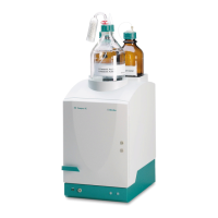
883 Basic IC plus
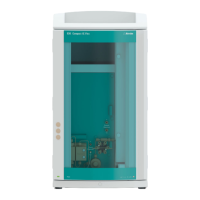
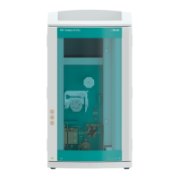
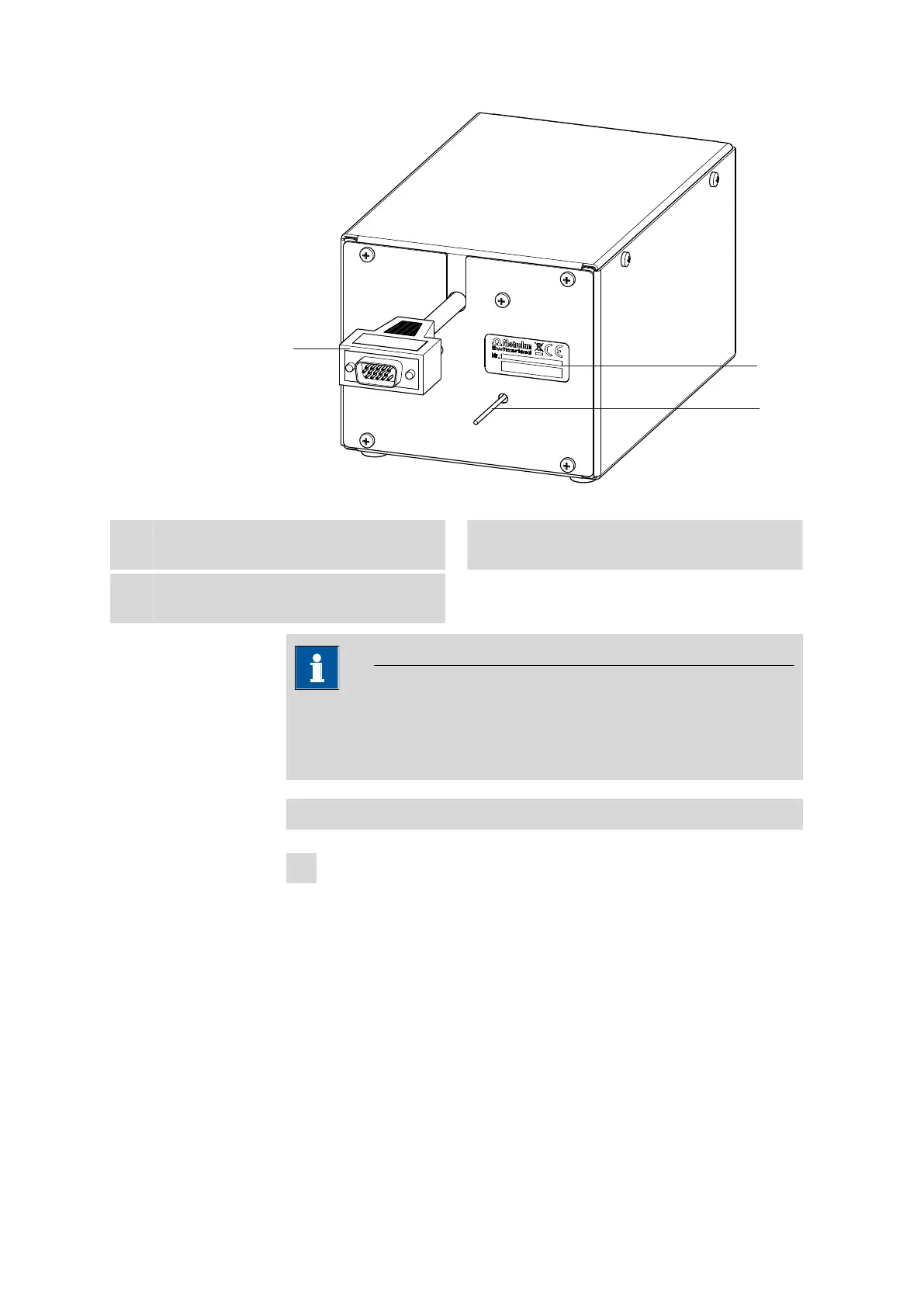
Figure 16 Rear of conductivity detector
1
Detector cable
With installed plug.
2
Detector output capillary
Permanently installed.
3
Type plate
With serial number.
NOTICE
In order to prevent unnecessary peak widening after separation, the
connection between the outlet of the separation column and the inlet
to the detector should be kept as short as possible.
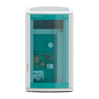
Connecting the detector input capillary to the suppressor
1
■ Connect the detector input capillary (17-1) and the capillary of
the MSM labeled out (17-2) to each other using a coupling
(6.2744.040) (17-3) and two short pressure screws (6.2744.070)
(17-4).