3.11 Installing the pulsation absorber
■■■■■■■■■■■■■■■■■■■■■■
28
■■■■■■■■
883 Basic IC plus
1
2
6.2744.070
6.2744.070
6.2821.120
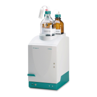
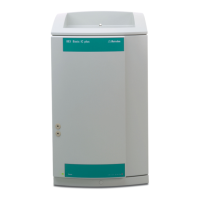
Figure 10 Inline filter
1
Inlet capillary
Connected to the purge valve.
2
Outlet capillary
Connected to the pulsation absorber.
The inline filter is completely connected. No installation work is required.
3.11 Installing the pulsation absorber
The pulsation absorber is installed between the high-pressure pump and
the injection valve. It protects the separation column from damage caused
by pressure fluctuations, e.g. when the injection valve is switched, and
reduces interfering pulsations during highly sensitive measurements.
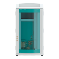
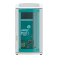
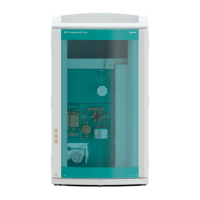
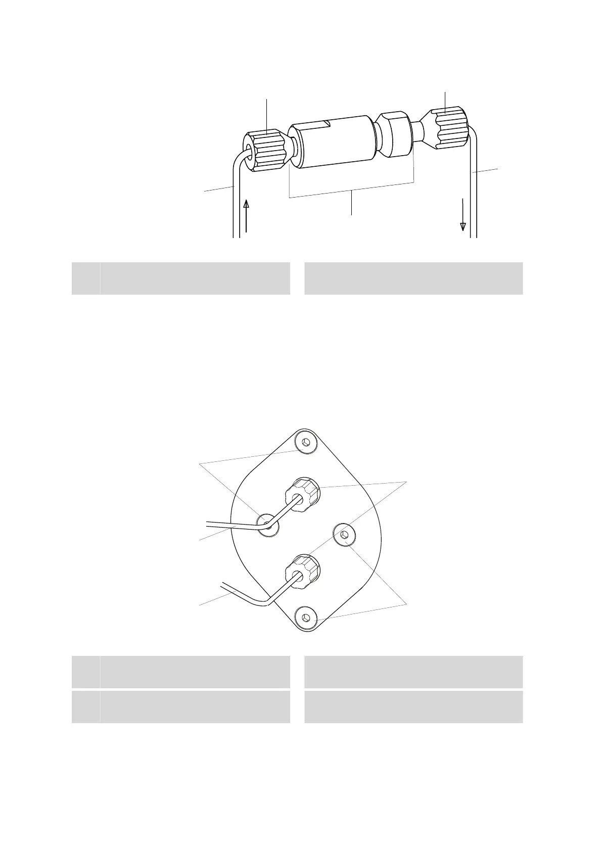
Figure 11
Pulsation absorber
1
Fastening screws
2
Connection capillary
Connection to injection valve.
3
Connection capillary
Connection to inline filter.
4
PEEK pressure screws, short
(6.2744.070)