■■■■■■■■■■■■■■■■■■■■■■
3 Installation
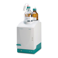
883 Basic IC plus
■■■■■■■■
11
■ Connect the separation column (see chapter 3.20, page 51).
– Connect the inlet of the separation column to the end of
the column inlet capillary or to the guard column (if used)
as described in the leaflet supplied with the separation col-
umn.
– Connect the capillary of the suppressor labeled in to the
outlet of the separation column using a pressure screw
(6.2744.070).
■ Hang the separation column with chip in the column holder of
the instrument.
10
Conditioning the instrument
(see chapter 3.21, page 54).
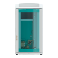
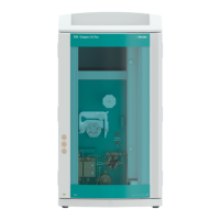
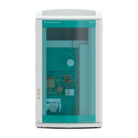
3.3 Installation diagram
The following installation diagram shows a schematic of the front of the
instrument after installation is complete. Some of the capillaries are
already installed when the instrument is delivered; these capillaries are not
numbered in the diagram. Numbered capillaries have to be connected
during installation.