3.2 Initial installation
■■■■■■■■■■■■■■■■■■■■■■
10
■■■■■■■■
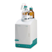
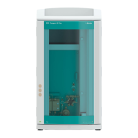
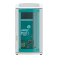
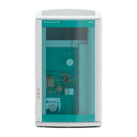
883 Basic IC plus
6
Connecting the suppressor
(see chapter 3.13.3, page 33)
■ Connect the capillary labeled regenerant (3-10) to the peristaltic
pump on the outlet end of the pump tubing for the regeneration
solution (3-9) using a pump tubing connection (6.2744.180)
(3-17) and a short pressure screw (6.2744.070) (3-15).
■ Connect the capillary labeled rinsing solution (3-12) and the
detector outlet capillary to each other using a coupling
(6.2744.040) and two short pressure screws (6.2744.070).
■ Connect the two capillaries of the suppressor labeled waste reg.
and waste rins. with the waste collector (6.5336.000).
7
Connecting the instrument
■ Connect the instrument to the PC using a USB cable (6.2151.020)
(see "Connecting the USB cable", page 45).
■ Connect the instrument to the power grid (see chapter 3.17,
page 46).
8
Initial start-up
(see chapter 3.18, page 47)
■ Switch on the PC and start MagIC Net.
■ Switch on the instrument.
■ Deaerate the high-pressure pump.
■ Adjust the contact pressure of the peristaltic pump.
■ Rinse the instrument without column(s).
9
Installing guard column and separation column
■ Remove the coupling (6.2744.040) between the column inlet
capillary and the eluent inlet capillary of the suppressor.
■ Cut the column inlet capillary (6.1831.100) (3-2) to the required
length with the capillary cutter (6.2621.080).
■ Optionally (to improve the measuring results): Cut off a piece of
the green EVA tubing (6.1806.100) that is 5 mm shorter than the
column inlet capillary and pull it over the column inlet capillary
(3-3).
■ Connect the guard column (optional) (see chapter 3.19, page
49).
– Connect the guard column to the end of the column inlet
capillary as described in the leaflet supplied with the guard
column.
– Rinse the guard column.