3.13 Suppressor
■■■■■■■■■■■■■■■■■■■■■■
32
■■■■■■■■
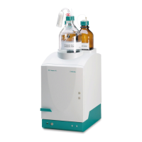
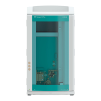
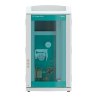
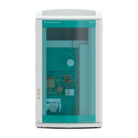
883 Basic IC plus
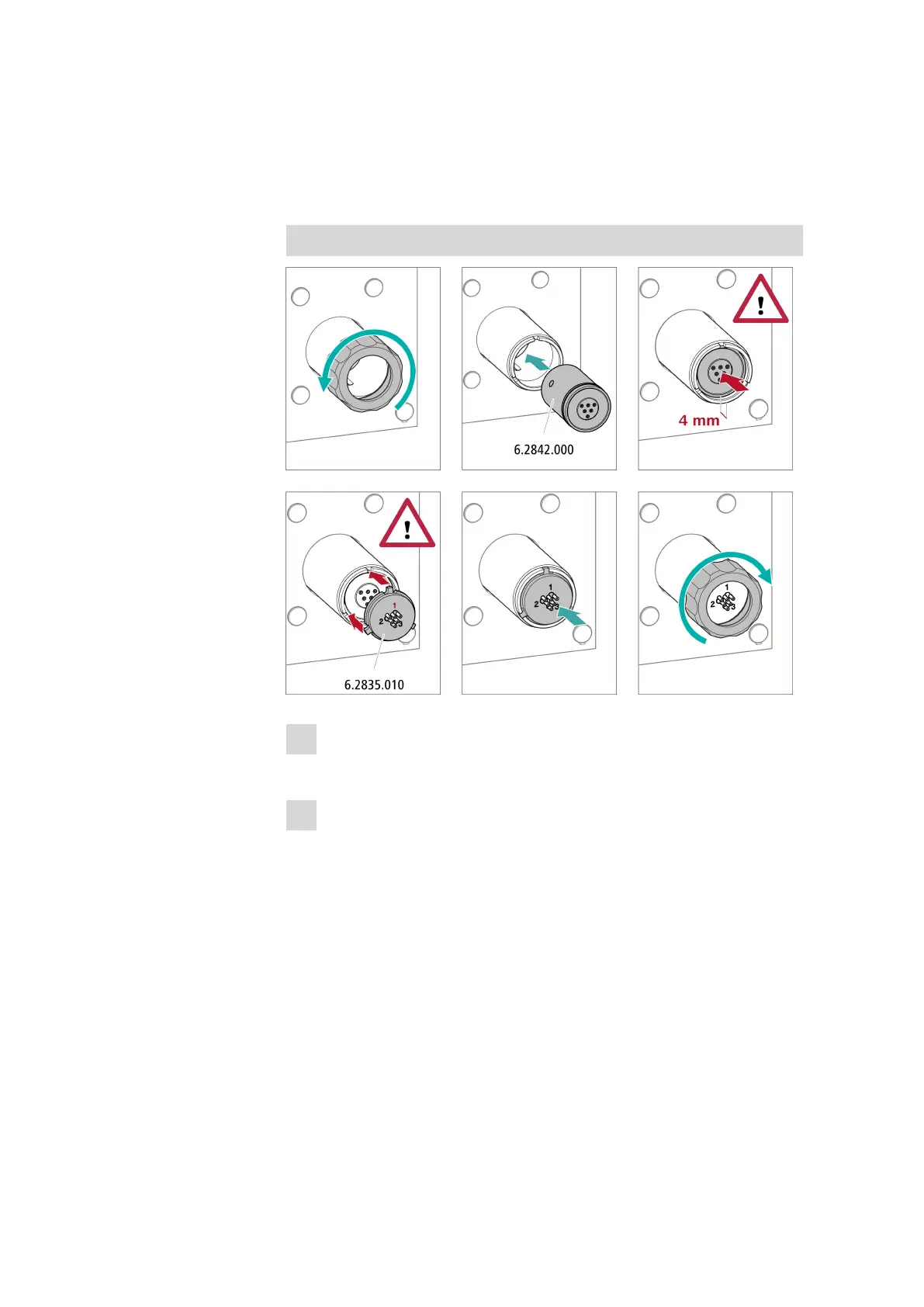
■ Insert the rotor into the adapter so that the tubing connections
on the rear of the rotor fit into the corresponding recesses inside
the adapter and one of the 3 holes of the rotor is visible in the
slot of the adapter.
Inserting the adapter into the suppressor drive
1
Removing the union nut
■ Loosen the union nut and remove it.
2
Inserting the rotor
■ Insert the adapter into the suppressor drive so that the tubing
connections on the rear of the adapter fit into the corresponding
recesses inside the suppressor drive and one of the 3 holes of the
rotor is visible from below in the slot of the suppressor drive.