Contents
Titrando Installation Instructions III
List of illustrations
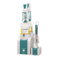
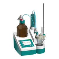
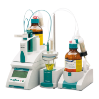
Fig. 1: The Titrando system ...................................................................................................... 1
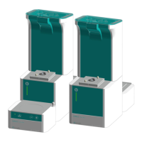
Fig. 2: Front view of a Titrando with internal dosing drive........................................................ 5
Fig. 3: Front view of a Titrando for the use of external dosing devices ................................... 6
Fig. 4: Rear view of the Titrando ...............................................................................................7
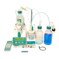
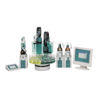
Fig. 5: Titrando – Peripheral devices ........................................................................................ 9
Fig. 6: Titrando – Touch Control ............................................................................................. 12
Fig. 7: Titrando – Computer .................................................................................................... 13
Fig. 8: Overview of MSB connections..................................................................................... 14
Fig. 9: Titrando – Stirrer........................................................................................................... 15
Fig. 10: Attaching the exchange unit to the Titrando ............................................................. 16
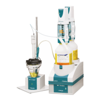
Fig. 11: Example for connecting a dosing device: Titrando – 800 Dosino ........................... 18
Fig. 12: Example for connecting a dosing device: Titrando – 805 Dosimat......................... 19
Fig. 13: Titrando – Remote box .............................................................................................. 20
Fig. 14: Titrando – Printer........................................................................................................ 21
Fig. 15: Titrando – USB-RS232 box – Balance....................................................................... 23
Fig. 16: Titrando –USB Sample Processor ............................................................................. 24
Fig. 17: Titrando – Titrando/Dosing Interface ......................................................................... 24
Fig. 18: Titrando – Sensors .....................................................................................................29
Fig. 19: Connecting the 854 iConnect .................................................................................... 29
Fig. 20: Recommended arrangement of magnetic stirring bar (1), electrode (2) and
buret tip (3) ...................................................................................................................30
Fig. 21: Drawing of the KF titration cell 6.5609.000................................................................ 31
Fig. 22: Arrangement of transport tip, buret tip and draw-off tip ........................................... 32