Page 66 Electrical installation
Product Manual / Mounting Instructions „Servo drives ARS 2320 FS, ARS 2340 FS and ARS 2360W FS“ Version 1.0
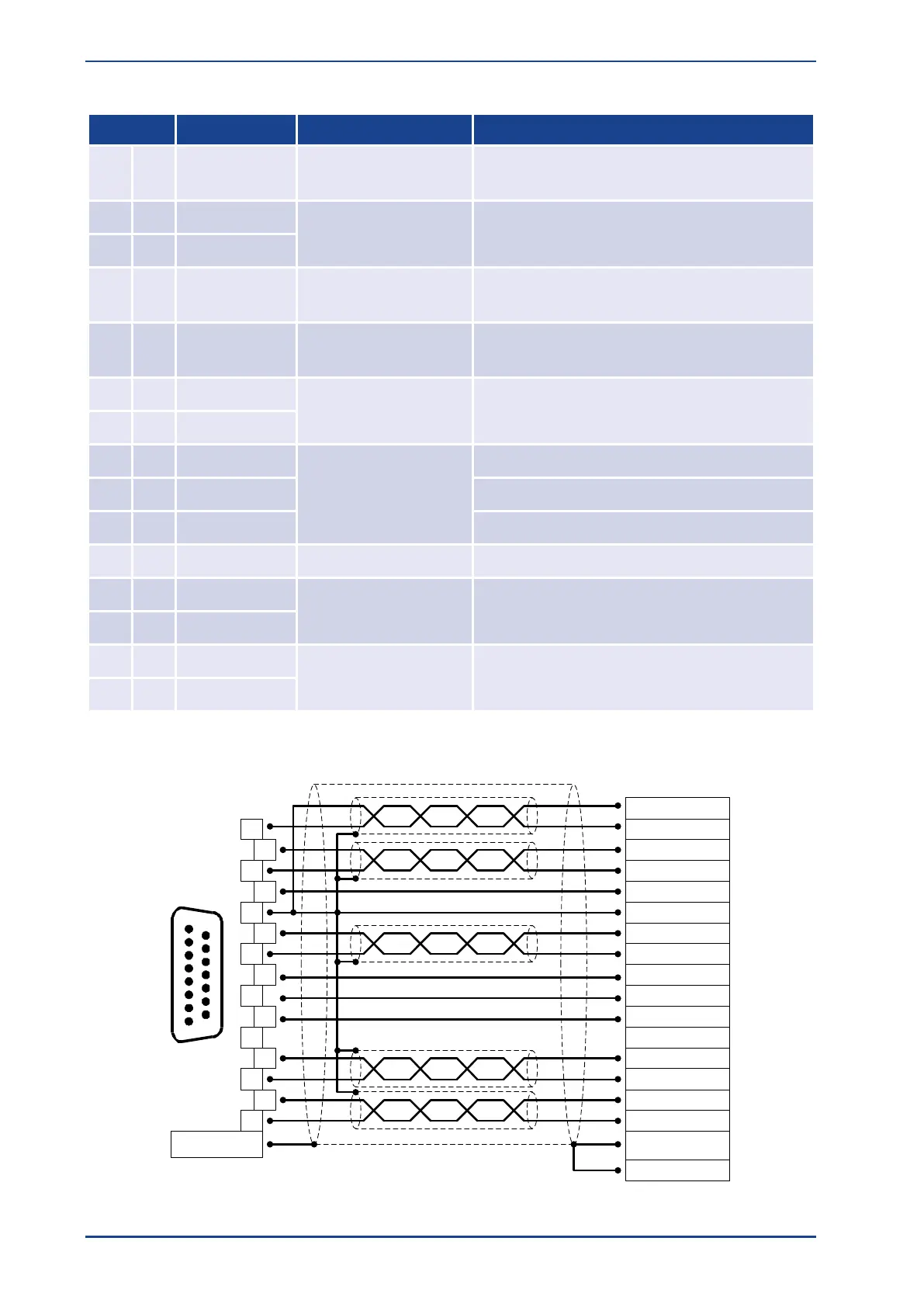
Pin assignment X2B Digital incremental encoder
Motor temperature sensor, normally closed
contact, PTC, NTC, KTY...
Sensor input for encoder supply
5 V / 12 V / 10%
I
max
= 300 mA
Reference potential Supply voltage and
motor temperature sensor
Reset pulse trace signal (differential) from
high-resolution incremental encoder
0 V / 5 V
RI 2 k
on VCC
Phase U hall sensor for commutation
Phase V hall sensor for commutation
Phase W hall sensor for commutation
A trace signal (differential) from digital
incremental encoder
B trace signal (differential) from digital
incremental encoder
Output of the digital incremental
encoder at the motor
D-SUB connector at
X2B
Cable shield
(optional)
Connector housing
Backplane
Control Cabinet
2
3
4
5
9
10
11
1
12
6
7
8
13
14
15
1
9
8
15
B#
B
GND
A
US
N
N#
SENSE-
A#
SENSE+
H_U
H_V
H_W
MT+
MT- (AGND)
Male
Figure 29: Pin assignment: Digital incremental encoder [X2B]
 Loading...

