29
www.roadwidener.com
Model SP-8 & 10
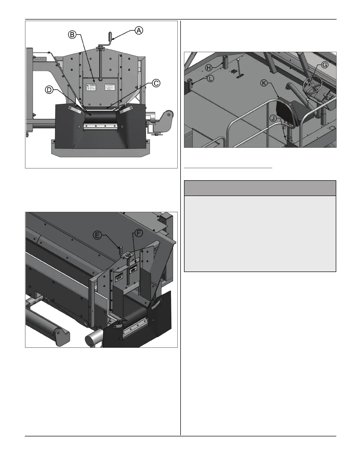
9. To adjust seat height, line up appropriate hole in
seat post with hole in mounting socket and insert
pin (I).
5.7.2 BlAde sIde CHAnGeover
^ WARNING
Prevent serious injury or death.
Before performing inspections, service or
maintenance:
• Park machine on rm, level surface and
engage parking brake.
• Switch engine off.
• Close and lock control panel cover.
• Chock tires.
1. Start machine as in section 5.2. If machine is in
motion, park machine on a rm level surface,
engage parking brake by pushing operator console
E-stop button fully down. Keep engine running.
2. Toggle conveyor direction switch on operator
console to right side.
3. Lower blade down to ground by toggling grade
switch on operator console.
4. Switch engine off.
5. Close and lock control panel cover.
6. Remove pin (A) and remove push tube (B) from
ball hitches on machine.
6. On left side of hopper, turn crank (E) clockwise
to lift gate (F) up as high as required for sufcient
material ow.
7. Use a suitable lifting device to lift operator console
assembly (G) from right side console mount socket
to install into console mount socket (H) on left side.
8. Remove pin (I) to lift seat assembly (J) from right
side mounting socket and insert into left side
mounting socket (K).