www.roadwidener.com
30
Model SP-8 &10
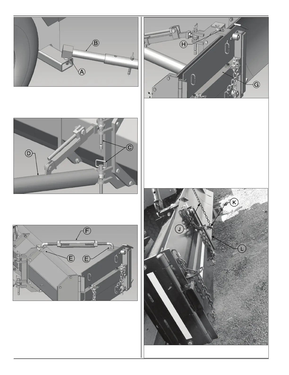
7. Remove pins (C) to release push tube (D) from
mounting bracket.
8. Remove cotter pins (E) to disengage outer edger
brace (F) from turnbuckle mounts.
9. Swing in outer edger assembly (G) until it is parallel
to length of blade.
10. Insert the locking hardware (H) in the turnbuckle
mount to hold the outer edger assembly in place.
11. Start engine as in section 5.2.
12. Toggle grade switch on operator console to lift blade
assembly to maximum stroke of grade cylinder.
13. Swing blade assembly inward until its length is
parallel to machine body.
14. Engage blade restraint assembly (J) with blade
assembly by inserting bracket (K) into lower edge
(L) of blade curved prole.