Technical Information
27
G 5xxx
3.5 G 557x, G 567x (Dimension with Incognito)
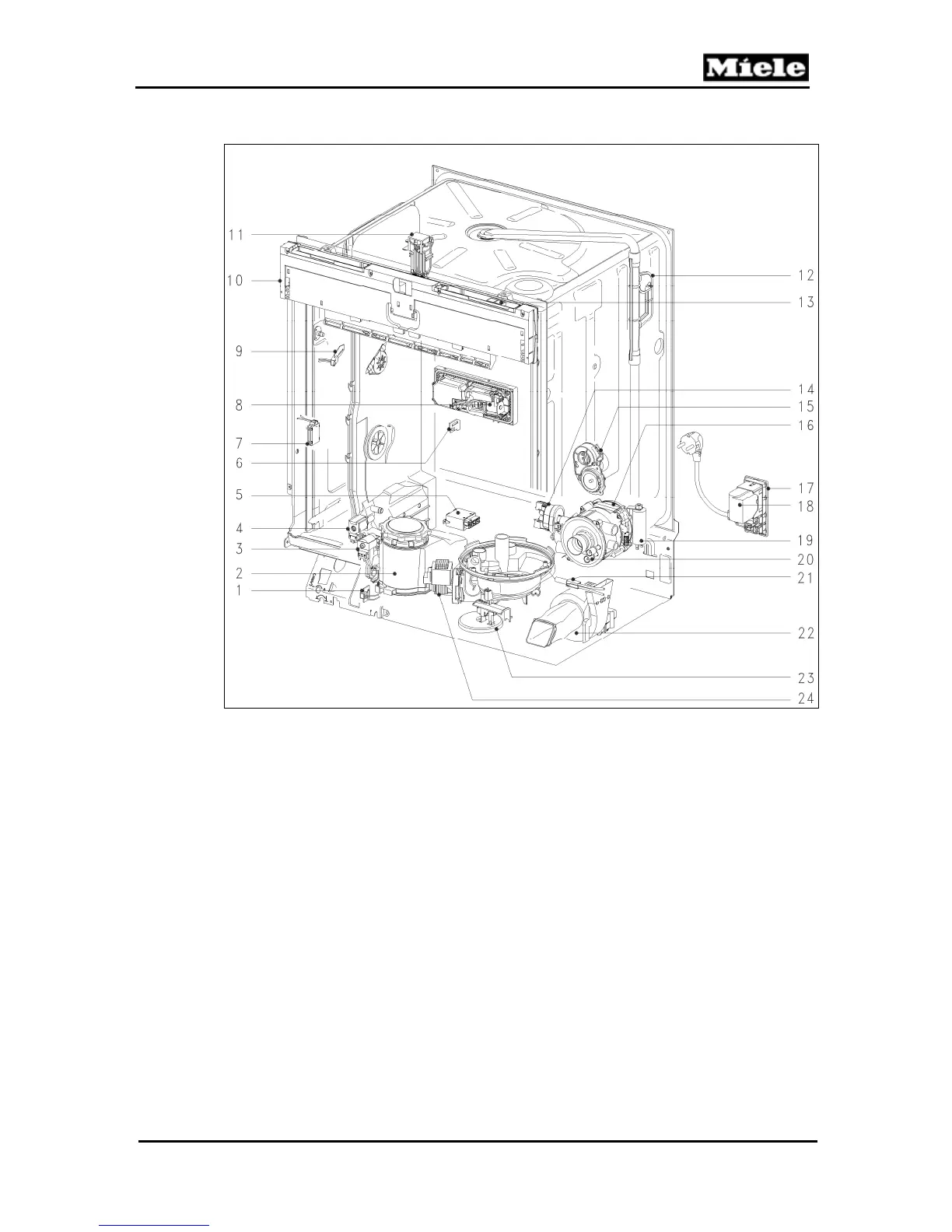
Figure D-10: G 557x, G 567x Component Layout
1
Salt float switch, B8/2
14
Heater pressure switch, B1/13
2
Salt container
15
Slide shutter, M24 and B3/12
3
Reactivation solenoid, Y38
16
Circulation pump (MPEW), M6
4
Wash-water hardness solenoid, Y5
17
Terminal block, X3/1
5
Heater relay, K1/1
18
Interference suppression, Z1
6
Rinse aid float switch, B8/1
19
Circulation pump capacitor, C6
7
Spray arm sensor
20
Heater, R1
8
Combination dispenser solenoid, Y50
21
Temperature sensor (NTC), R30
9
Flow meter, B3/4
22
Fan, M2
10
Electronic modules, 1N1 and 2N1
23
Overflow float switch, B8/3
11
Door contact switch, S24
24
Drain pump, M8
12
Turbidity sensor, B3/10
Not shown
Inlet valve, Y63
(in base of appliance)
13
Main switch, S2