Technical Information
88
G 5xxx
accordingly with regard to water quantity, program duration and temperature.
Note:
In addition, temperature compensation of the Autosensor is carried out via
an integrated NTC resistor.
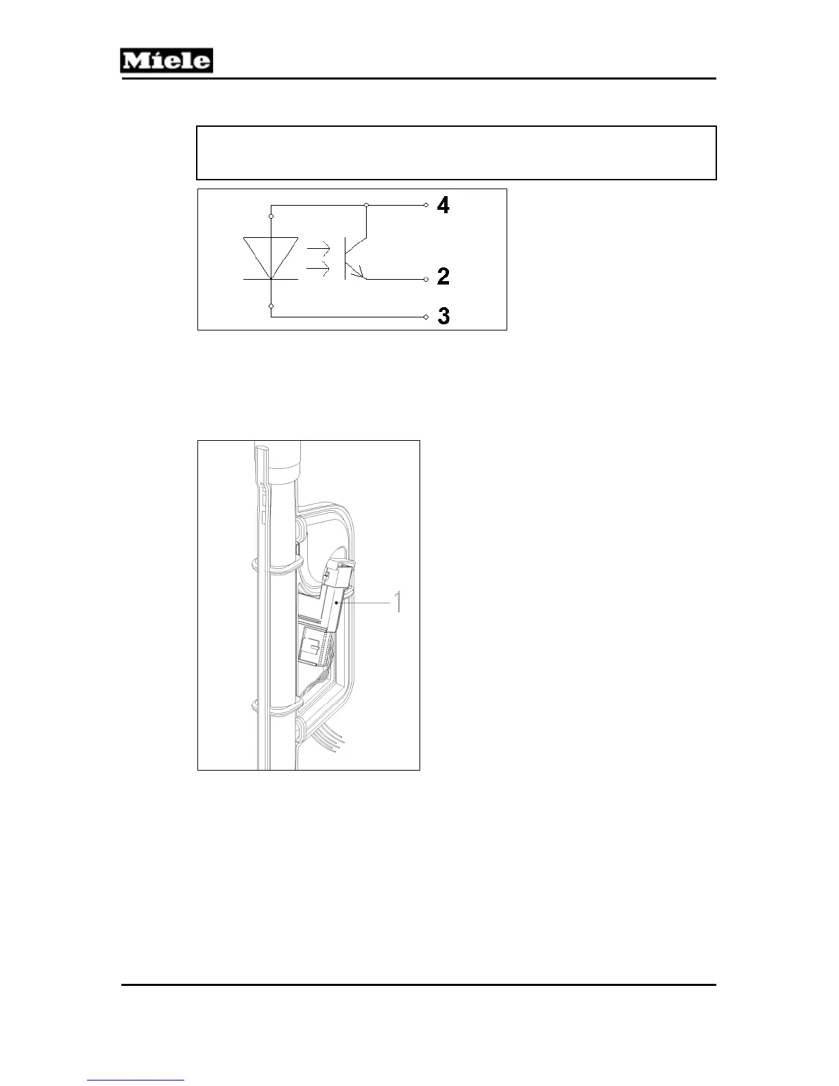
Figure 050-13: Turbidity Sensor Circuit
2
Light receiver output (emitter)
3
IR LED cathode
4
Common 5V
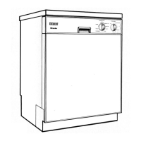
The sensor is situated in the feed pipe to the top spray arm; see Figure 050-14,
Item 1.
Figure 050-14: Turbidity Sensor Location
The flow rate is approximately 4 gallons (15 liters) per minute. In order to
compensate for residues on the sensor and aging of the optical system, the
turbidity sensor must be recalibrated regularly. This process is carried out
automatically by the electronic and cannot be modified in any way.
Measurements are carried out at different times during the pre-wash, main
wash and interim rinse stages. For this the top and bottom spray arms must
be supplied with water.