Technical Information
74
G 5xxx
2 Function
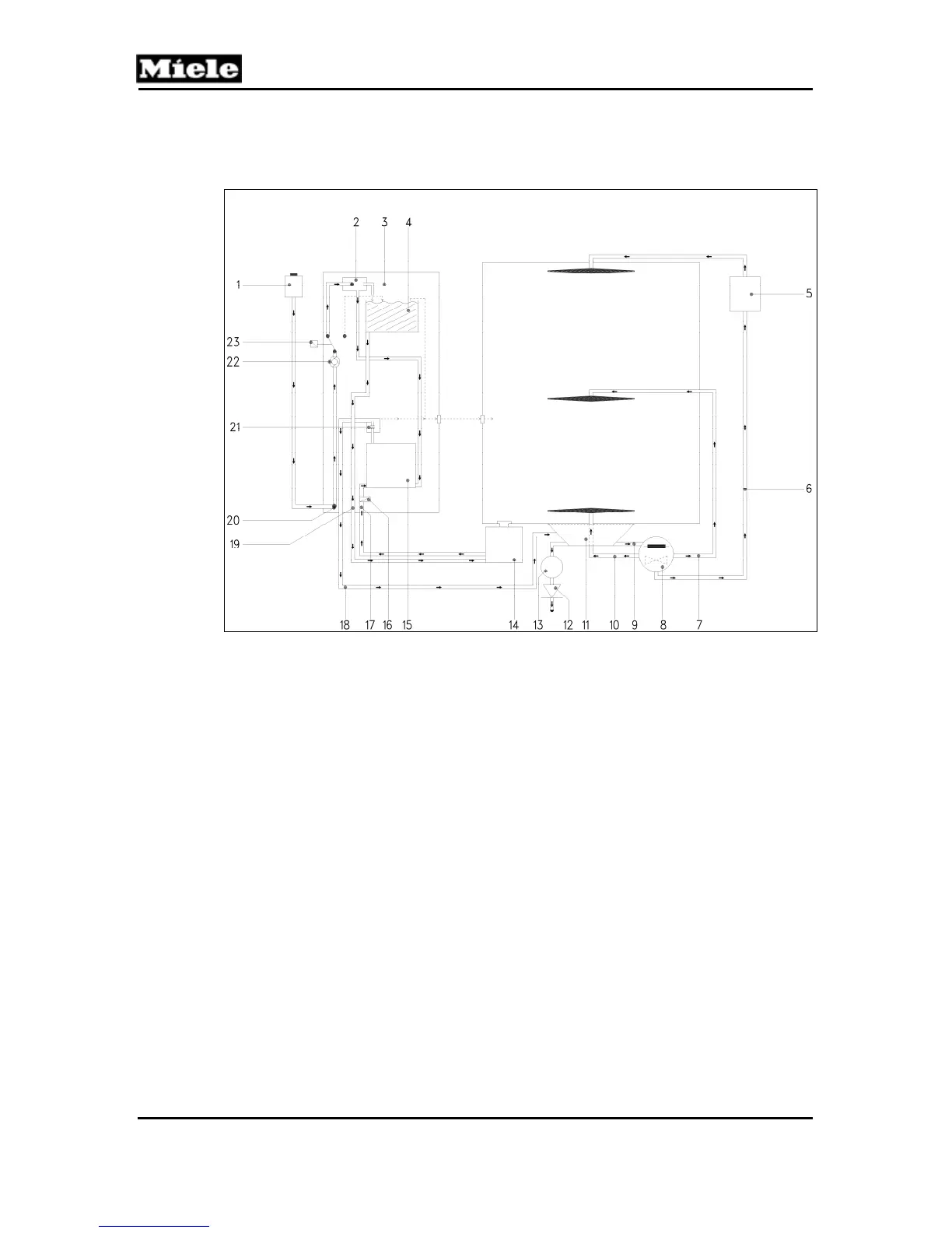
2.1 Water Circulation
Figure 050-1: Water Paths - Diagram
1
Inlet valve Y63
13
Drain pump M8
2
Ball valve
14
Salt container
3
Water diverter
15
Ion replacement
4
Softener reactivation water reservoir
16
Reactivation solenoid Y38
5
Turbidity sensor B3/10
17
Intake from salt container
6
Top spray arm feed pipe
18
Soft-water outlet to sump
7
Middle spray arm feed pipe
19
Water outlet to salt container
8
Circulation pump M6 + heater R1
20
Supply to water diverter
9
Feed to circulation pump
21
Non-return valve
10
Bottom spray arm feed pipe
22
Flow meter B3/4
11
Sump
23
Wash water hardness solenoid Y5 (EGS)
12
Non-return valve
Water is drawn into the system from the cabinet sump by a circulation pump
and is then passed to the top, middle, and bottom spray arms. The water then
sprays over the load and passes via a filter system back into the sump again.