Technical Information
7
G 5xxx
List of Figures
Figure D-1: Touchtronic Fascia Panel (G 5505/G 5705 Shown) ................................................... 19
Figure D-2: Incognito Fascia Panel (G 427x/G 4570/G 5175 Shown) .......................................... 20
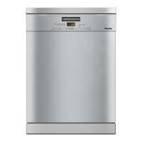
Figure D-3: Navitronic Fascia Panel (G 5915 Shown) .................................................................. 20
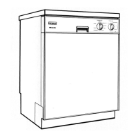
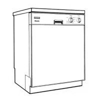
Figure D-4: Integrated Model ......................................................................................................... 21
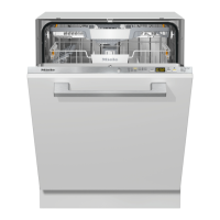
Figure D-5: Fully Integrated Model ................................................................................................ 22
Figure D-6: G 4205/G 45x0 Component Layout ............................................................................ 23
Figure D-7: G 5105, G 5225 Component Layout .......................................................................... 24
Figure D-8: G 5505, G 5605, G 5705 Component Layout ............................................................ 25
Figure D-9: G 427x, G 428x, G 4570, G 5175, G 5285 Component Layout ................................. 26
Figure D-10: G 557x, G 567x Component Layout ......................................................................... 27
Figure D-11: G 5775 Component Layout ...................................................................................... 28
Figure D-12: G 5975 Component Layout ...................................................................................... 29
Figure D-13: G 5915 Component Layout ...................................................................................... 30
Figure D-14: Data Tag Location .................................................................................................... 31
Figure D-15: Data Tag Information ................................................................................................ 31
Figure D-16: Model Numbering ..................................................................................................... 31
Figure 010-1: Side Panel Removal ................................................................................................ 34
Figure 010-2: Drip Pan Removal ................................................................................................... 35
Figure 010-3: Opening the Hinge Bracket ..................................................................................... 35
Figure 010-4: Front Hinge Retaining Screw .................................................................................. 36
Figure 010-5: Side Hinge Retaining Screw ................................................................................... 36
Figure 010-6: BrilliantLight Circuit Board and Plug ....................................................................... 37
Figure 010-7: BrilliantLight Lens .................................................................................................... 38
Figure 020-1: Door Handle Release .............................................................................................. 40
Figure 020-2: Child Safety Lock .................................................................................................... 40
Figure 020-3: Drying Plus (before Program End) .......................................................................... 41
Figure 020-4: Drying Plus (after Program End) ............................................................................. 42
Figure 020-5: Door Lock Latch Plugs ............................................................................................ 42
Figure 020-6: Door Lock Latch, Position 1 .................................................................................... 43
Figure 020-7: Door Lock Latch, Position 2 .................................................................................... 44
Figure 020-8: Door Lock Latch, Position 3 .................................................................................... 45
Figure 020-9: Door Lock Latch, Intermediate Opening Position ................................................... 46
Figure 020-10: Door Lock Latch, Intermediate Closing Position ................................................... 47
Figure 020-11: Door Lock Latch Assembly (Mechanical Version) ................................................ 48
Figure 020-12: Combination Dispenser ......................................................................................... 48
Figure 020-13: Combination Dispenser Removal ......................................................................... 51
Figure 020-14: Door Seal with Door .............................................................................................. 52
Figure 020-15: Bottom Door Seal .................................................................................................. 53
Figure 020-16: Door Lock Removal (Integrated Models) .............................................................. 54
Figure 020-17: Door Lock Emergency Release ............................................................................ 55
Figure 020-18: Automatic Door Opener, Viewed from Underside ................................................. 56
Figure 020-19: Drive ...................................................................................................................... 57
Figure 030-1: Integrated Door Panel Screw Locations ................................................................. 59
Figure 030-2: Door Tension Adjustment ....................................................................................... 59
Figure 030-3: Outer Door Panel Removal ..................................................................................... 60
Figure 030-4: Lower Access Cover Plate and Connecting Strip Removal .................................... 61
Figure 030-5: Terminal Block Cover .............................................................................................. 62
Figure 030-6: Terminal Block Screws............................................................................................ 62
Figure 030-7: Interference Suppression Capacitor and Ground Wire ........................................... 63
Figure 040-1: Recirculation Turbothermic Drying .......................................................................... 65