OM-281426 Page 19
F
Complete Parts List is available at www.MillerWelds.com
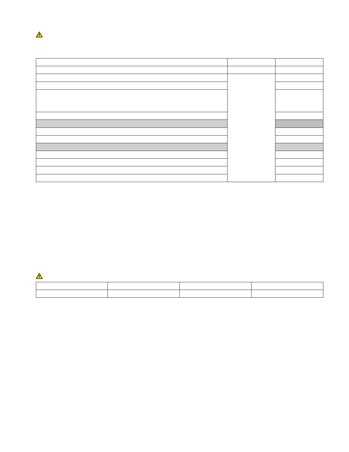
5-3. Electrical Service Guide
Failure to follow these electrical service guide recommendations could create an electric shock or fire hazard. These recommen-
dations are for an individual branch circuit sized for the rated output and duty cycle of one welding power source. In individual
branch circuit installations, the National Electrical Code (NEC) allows the receptacle or conductor rating to be less than the rating
of the circuit protection device. All components of the circuit must be physically compatible. See NEC articles 210.21, 630.11, and
630.12.
50/60 Hz 1–Phase 50/60 Hz 1–Phase
Rated Supply Voltage (V) 120 240
Rated Maximum Supply Current I
1max
(A)
A 15 or 20 ampere in-
dividual branch cir-
cuit protected by
time-delay fuses or
circuit breaker is re-
quired. See Section
5-5.
32
Rated Effective Supply Current I
1eff
(A) 15
Maximum Recommended Standard Fuse Rating In Amperes
1
Time Delay Fuses
2
40
Normal Operating Fuses
3
45
Maximum Recommended Supply Conductor Length In Feet (Meters)
4
34 (10)
Raceway Installation
Minimum Supply Conductor Size In AWG (mm
2
)
5
12 (4)
Minimum Grounding Conductor Size In AWG (mm
2
)
5
12 (4)
Flexible Cord Installation
Minimum Supply Conductor Size In AWG (mm
2
)
6
12 (4)
Minimum Outside Diameter Of Cord In Inches (mm) .525
Maximum Outside Diameter Of Cord In Inches (mm) .550
Recommended Strain Relief
7
See Parts List
Reference: 2023 National Electrical Code (NEC) (including article 630)
1 If a circuit breaker is used in place of a fuse, choose a circuit breaker with time-current curves comparable to the recommended fuse.
2 "Time-Delay" fuses are UL class "RK5" . See UL 248.
3 "Normal Operating" (general purpose - no intentional delay) fuses are UL class "K5" (up to and including 60 amps), and UL class "H" ( 65 amps
and above). See UL 248.
4 Maximum total length of copper supply conductors in entire installation, raceway and/or flexible cord.
5 Raceway conductor data in this section specifies conductor size (excluding flexible cord or cable) between the panelboard and the equipment
per NEC Table 310.16 and is based on allowable ampacities of insulated copper conductors having a temperature rating of 75°C (167°F) with
not more than three single current-carrying conductors in a raceway.
6 Flexible cord conductor size is based on NEC Table 400.5(A)(1) for SOOW 600V 90°C (194°F) jacketed cable in a 30°C (86°F) ambient tem-
perature. See NEC Table 310.15(B)(1)(1) for ambient temperature correction factors. Flexible cord used for connection to the power supply sys-
tem shall comply with the requirements of UL 62.
7 If necessary, have a qualified person enlarge access hole in machine panel to accommodate strain relief.
5-4. Input Power Extension Cord Data
Use extension cord only for temporary wiring. Remove extension cord immediately after completing the project.
Cord Type Minimum Conductor Size Number Of Conductors Maximum Cord Length
Heavy Duty (Hard Usage) 12 AWG (4 mm
2
) 3 50 ft (15 m)
F
Read OSHA Standard 1910.334 for more information on the use of cord and plug connected equipment.
Read National Electrical Code (NEC) Article 590 for more information on temporary wiring.