OM-281426 Page 25
F
Complete Parts List is available at www.MillerWelds.com
5-10. MIG Welding Connections
A complete Parts List is available at www.MillerWelds.com
OM-281426 Page 14
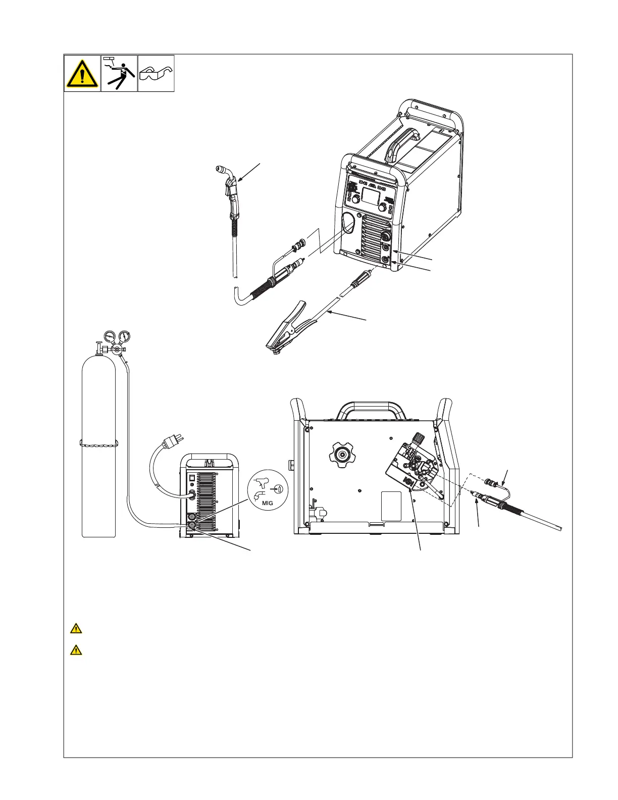
2-7. MIG Welding Connections
Ref. 275172A / Ref. 275167A / Ref. 275168A
4
3
1
2
8
6
7
5
Turn off unit and disconnect input
power before making connections.
Do not use worn, damaged, under-
sized, or repaired cables.
1 Weld Output Receptacle
2 Work Clamp Receptacle
3 MIG Gun
4 Work Clamp And Cable
Connect work cable to work receptacle. Turn
connector clockwise.
Ensure all connections are tight.
5 Gun End
Connect gun end to drive assembly (see
Section 5-11).
6 Trigger Control Cable
7 Four Pin Trigger Control Cable
Receptacle
Route trigger control cable through MIG gun
hole.
Connect plug on end of cable to four pin re-
ceptacle inside unit.
8 MIG Shielding Gas Connection
Use 75/25 mix or CO
2
shielding gas for solid
wire. Use Argon shielding gas for aluminum
wire with spool gun (see Section 5-12).