OM-281426 Page 39
F
Complete Parts List is available at www.MillerWelds.com
6-11. Spoolmate
™
24 Inch Calibration (Menu 3 Of 12)
A complete Parts List is available at www.MillerWelds.com
OM-281426 Page 28
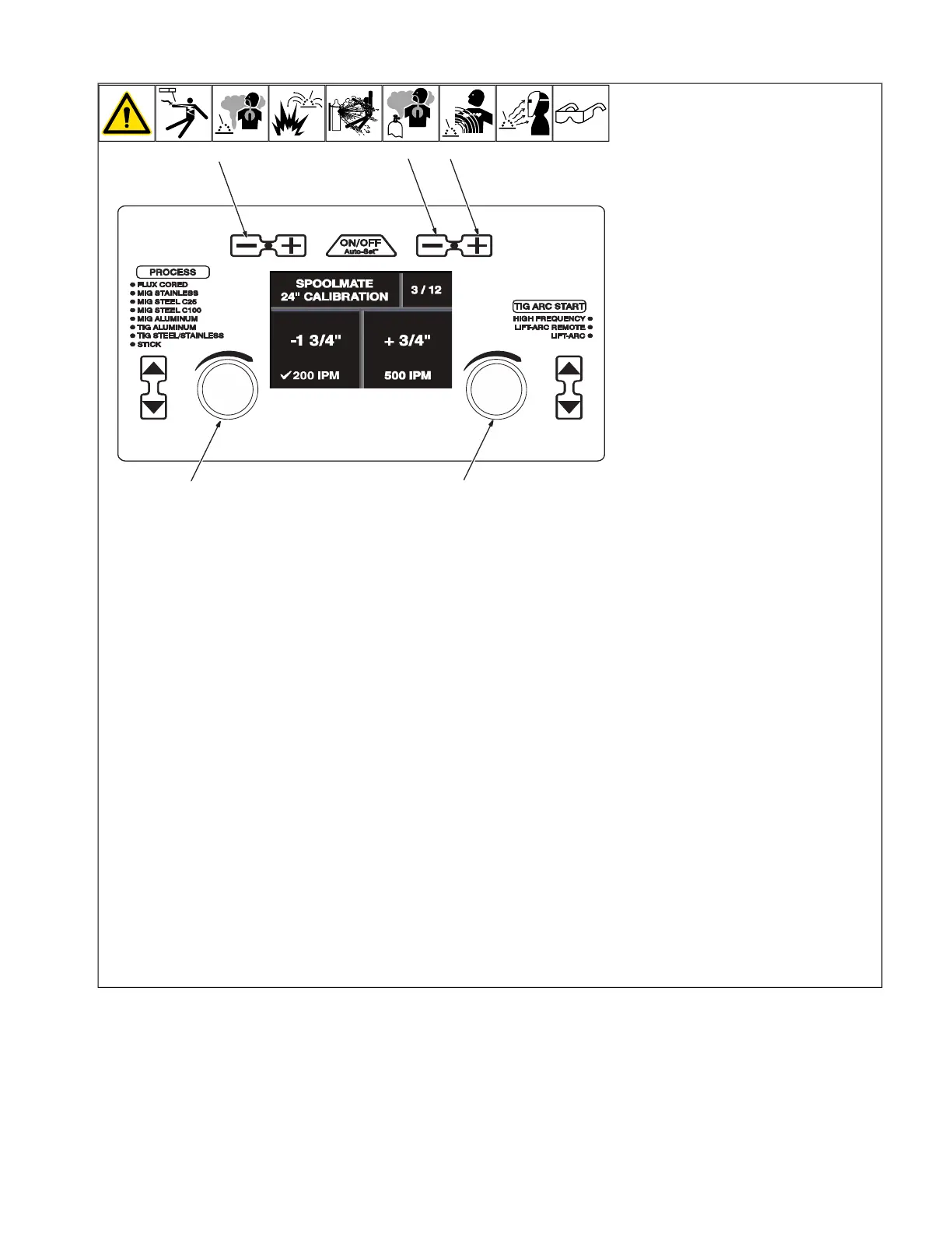
3-11. Spoolmate 24 Inch Calibration (Menu 3 Of 12)
Ref. 281252A
1
23
4 5
3-12. Spoolmate Run-In Speed (Menu 4 Of 12)
Ref. 281252A
1
2 3
1 Wire/Rod/Tungsten Minus (-) Button
2 Material Thickness Plus (+) Button
3 Material Thickness Minus (-) Button
4 Left Adjustment Knob
5 Right Adjustment Knob
F
Spoolmate 100 and 150 drive motors
are unique to this welding power
source. Motor calibration is necessary
any time a different Spoolmate 100 or
150 is connected to the Multimatic 220.
Connect Spoolmate to unit.
Cut wire flush at nozzle.
Follow instructions in Section 6-8 to enter
the setup menu.
To perform a Spoolmate calibration 24 in.
run-out test at 200 ipm, turn left Adjustment
knob, and verify that a check mark appears
next to 200 ipm.
Cut wire flush at nozzle and then trigger the
Spoolmate.
Spoolmate will feed approximately 24 in. of
wire through gun.
Cut wire flush at nozzle and measure run-
out.
If wire length is not 24 in., use left Adjust-
ment knob to increase/decrease length of
the run-out.
To perform a Spoolmate calibration 24 in.
run-out test at 500 ipm, turn right Adjustment
knob and verify that a check mark appears
next to 500 ipm.
Cut wire flush at nozzle and then trigger the
Spoolmate.
Spoolmate will feed approximately 24 in. of
wire through gun.
Cut wire flush at nozzle and measure run-
out.
If wire length is not 24 in., use right Adjust-
ment knob to increase/decrease length of
the run-out.
To exit menu, simultaneously press and re-
lease the Wire/Rod/Tungsten Minus (-) but-
ton and Material Thickness Plus (+) button,
or turn unit off and on.