OM-281426 Page 38
F
Complete Parts List is available at www.MillerWelds.com
6-9. Internal Motor 24 Inch Calibration (Menu 1 Of 12)
A complete Parts List is available at www.MillerWelds.com
OM-281426 Page 27
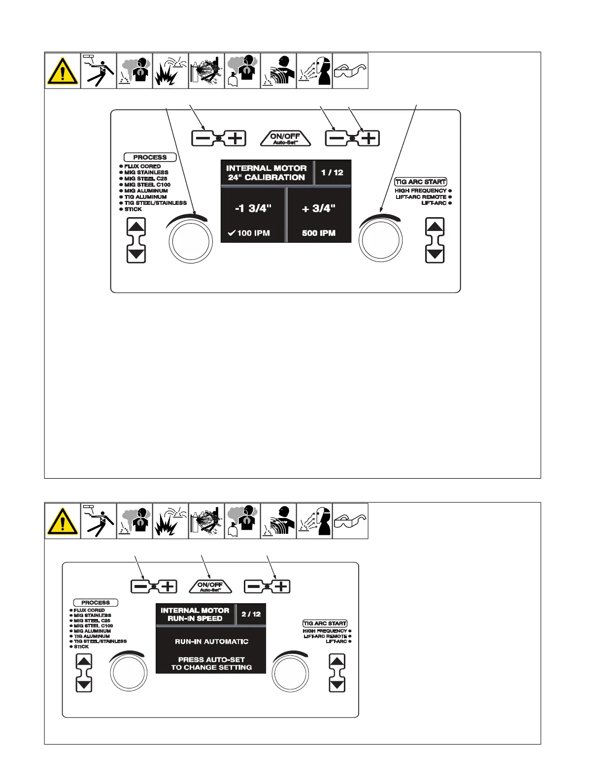
3-9. Internal Motor 24 Inch Calibration (Menu 1 Of 12)
Ref. 281252A
1
3
2
4
5
3-10. Internal Motor Run-In Speed (Menu 2 Of 12)
Ref. 281252A
1
2
3
F
The unit’s internal drive motor is cali-
brated at the factory. No calibration is
needed unless drive motor or control
board is changed.
1 Wire/Rod/Tungsten Minus (-) Button
2 Material Thickness Plus (+) Button
3 Material Thickness Minus (-) Button
4 Left Adjustment Knob
5 Right Adjustment Knob
Cut wire flush at nozzle.
Follow instructions in Section 6-8 to enter
the setup menu.
To perform a motor calibration 24 in. run-out
test at 100 ipm, turn left Adjustment knob,
and verify that a check mark appears next to
100 ipm.
Be sure wire is cut flush at nozzle, then trig-
ger the MIG gun. Motor will feed approxi-
mately 24 in. of wire through gun.
Cut wire flush at nozzle and measure run-
out. If length of run-out is not 24 in., turn left
Adjustment knob to increase/decrease
length of run-out.
To perform a motor calibration 24 in. run-out
test at 500 ipm, turn right Adjustment knob,
and verify that a check mark appears next to
500 ipm.
Be sure wire is cut flush at nozzle, then trig-
ger the MIG gun. Motor will feed approxi-
mately 24 in. of wire through gun.
Cut wire flush at nozzle and measure run-
out. If length of run-out is not 24 in., turn
right Adjustment knob to increase/decrease
length of run-out.
To exit menu, simultaneously press and re-
lease the Wire/Rod/Tungsten Minus (-) but-
ton and Material Thickness Plus (+) button,
or turn unit off and on.
6-10. Internal Motor Run-In Speed (Menu 2 Of 12)
A complete Parts List is available at www.MillerWelds.com
OM-281426 Page 27
3-9. Internal Motor 24 Inch Calibration (Menu 1 Of 12)
Ref. 281252A
1
3
2
4
5
3-10. Internal Motor Run-In Speed (Menu 2 Of 12)
Ref. 281252A
1
2
3
1 Wire/Rod/Tungsten Minus (-) Button
2 Auto-Set Button
3 Material Thickness Plus (+) Button
Follow instructions in Section 6-8 to enter
the setup menu.
To change the run-in setting, press the Auto-
Set button.
Run-in is the wire speed prior to the welding
arc being struck. When set to Automatic, the
welder determines the optimal run-in speed
for each start. When set to disabled, the run-
in speed is the same as the weld wire speed.
To exit the menu, simultaneously press and
release the Wire/Rod/Tungsten Minus(-) but-
ton and Material Thickness Plus (+) button,
or turn unit off and on.