OM-281426 Page 27
F
Complete Parts List is available at www.MillerWelds.com
5-12. Connecting Shielding Gas Supply
A complete Parts List is available at www.MillerWelds.com
OM-281426 Page 16
2-9. Connecting Shielding Gas Supply
Ref. 804 654-A / 282718A
1
2
3
1
2
4
1
2
10
12
11
9
5
6
5
6
9
7
8
MIG
TIG
OM-222 Page 1
allen_wrench
NGO’s
tools/
flathead philips head wrench
pliers
knife
heavy-duty workclamp light-duty workclamp wirecutter frontcutter
allen_set
needlenose
steelbrush nutdriver
chippinghammer
so
lderiron
stripcrimp
drill
torque wrench
socket wrench
hammer awl file
crimper
paintbrush
feelergauge flashlight ruler
toothbrush
greasegun
qtip (swab)
vicegrip
handream
punch
filterwrench
strapwrench
airgun
solvent pinextractor eprompuller pipewrench
torque screwdriver
crescent wrench
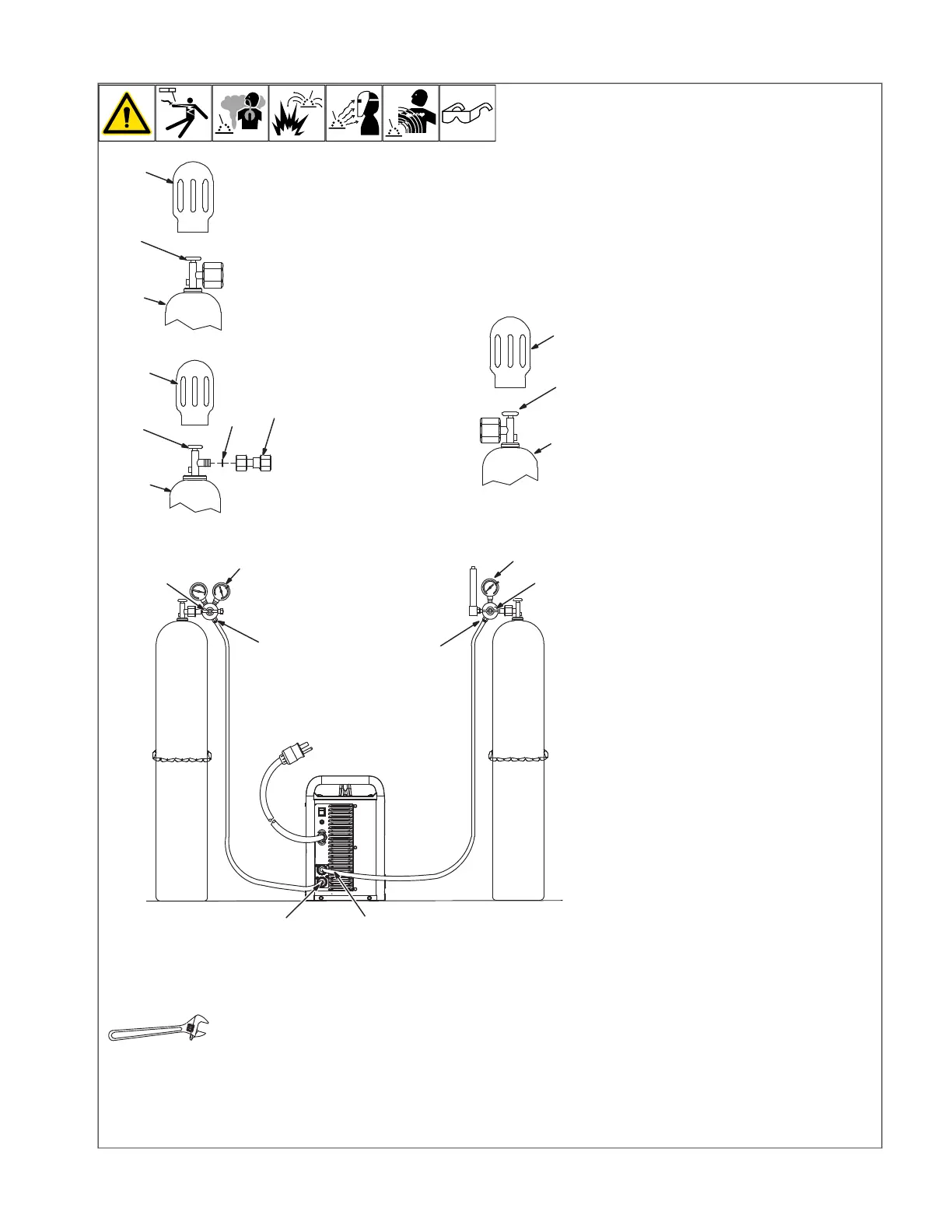
Obtain gas cylinder and chain to running
gear, wall, or other stationary support so cyl-
inder cannot fall and break off valve.
1 Cap
2 Cylinder Valve
Remove cap, stand to side of valve, and
open valve slightly. Gas flow blows dust and
dirt from valve. Close valve.
3 Cylinder—Mixed Gas
4 Cylinder—Argon Gas
5 Regulator/Flowmeter
Install Regulator/Flowmeter so face is
vertical.
6 Regulator/Flowmeter Gas Hose
Connection
7 Welding Power Source CO
2
And Mixed
Gas Hose Connection
8 Welding Power Source Argon Gas Hose
Connection
Connect gas hose between regulator/flow-
meter gas hose connection, and the appro-
priate fitting for the gas type on rear of
welding power source.
9 Flow Adjust
Typical flow rate for CO
2
shielding gas and
MIG (GMAW) welding is 15 to 30 CFH (cubic
feet per hour) and mixed gas is 25 to 45
CFH.
Typical flow rate for Argon shielding gas and
TIG (GTAW) welding is 15 to 25 CFH and
aluminum MIG (GMAW) welding is 35 to 45
CFH. Check wire manufacturer’s recom-
mended flow rate.
10 Cylinder—CO
2
Gas
11 CO
2
Adapter (Customer Supplied)
12 O-Ring (Customer Supplied)
Install adapter with O-ring between regula-
tor/flowmeter and CO
2
cylinder.