OM-281426 Page 57
Wire Size Amperage Range Recommended Wire Feed Speed Wire Feed Speed *
0.023 in. (0.58 mm) 30-90 A 3.5 in. (89 mm) per amp 3.5 x 62.5 A = 219 ipm (5.56 mpm)
0.030 in. (0.76 mm) 40-145 A 2 in. (51 mm) per amp 2 x 62.5 A = 125 ipm (3.19 mpm)
0.035 in. (0.89 mm) 50-180 A 1.6 in. (41 mm) per amp 1.6 x 62.5 A = 100 ipm (2.56 mpm)
*62.5 A based on 1/16 in. (1.6 mm) material thickness. ipm = inches per minute; mpm = meters per minute
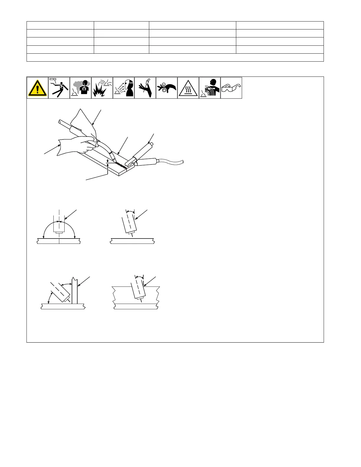
12-3. Holding And Positioning Welding Gun
OM-4419 Page 1
SECTION 1 GMAW WELDING (MIG) GUIDELINES WHEN
USING A VOLTAGE-SENSING FEEDER
1
2
3
4
5
6
7
8
2
3
5
4
90° 90°
0°-15°
45°
45°
1
0°-15°
1-1. Holding And Positioning Welding Gun
6 7 6 7
Groove Welds
90
°
90
°
0
°
-15
°
45
°
45
°
0
°
-15
°
6 7 6 7
Fillet Welds
90
°
90
°
0
°
-15
°
45
°
45
°
0
°
-15
°
6 7 6 7
F
Welding wire is energized when gun
trigger is pressed. Before lowering hel-
met and pressing trigger, be sure wire
is no more than 1/2 in. (13 mm) past
end of nozzle, and tip of wire is posi-
tioned correctly on seam.
1 Hold Gun and Control Gun Trigger
2 Workpiece
3 Work Clamp
4 Electrode Extension (Stickout)
Solid Wire – 3/8 to 1/2 in. (9 to 13 mm)
5 Cradle Gun and Rest Hand on
Workpiece
6 End View Of Work Angle
7 Side View Of Gun Angle