Functional Tests Periodic Maintenance
3 - 24 046-001141-00 A5/A3™ Service Manual
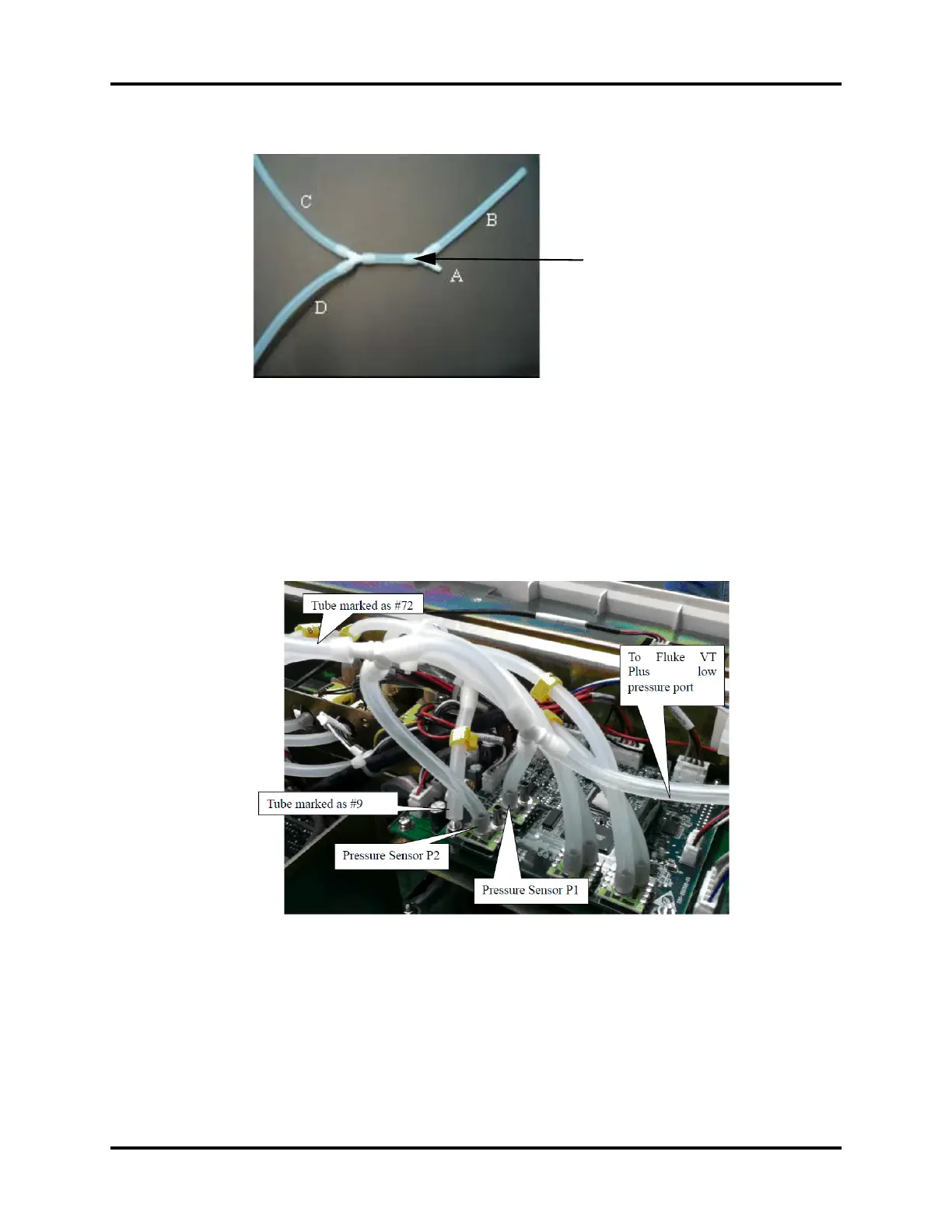
FIGURE 3-25 Pneumatic Connections for Four-Way Device
1. Remove the top cover (3 captive screws).
2. Remove the two tubes marked as #72 and #9 from the pressure sensors (refer to figure
below).
3. Connect the four way tube to the pressure sensor P1 of monitor board, pressure sensor P2 of
PEEP, the tube marked as #72, and the low pressure port of Fluke VT-Plus. The tube marked as
#9 will remain unconnected for this calibration.
FIGURE 3-26 Pneumatic Connections to Monitor Board
Four-way device connecting the
sampling lines for pressure
A
B
C
D