A5/A3™ Service Manual 046-001141-00 1 - 27
Theory of Operation Gas Flow
The above picture shows the CGO assembly. The CGO assembly includes a flow restrictor (21) and a
pressure relief valve (29). Flushed O2 and fresh gas that are mixed enter the CGO. The pressure relief
valve (29) at the front restricts the pressure of flushed O2, and also restricts the fresh gas from
exceeding 37.9 kPa.
1.3.4.9 Auxiliary O2 and Air Supply Assembly
The Auxiliary O2 Supply Assembly (51) and Auxiliary Air Supply Assembly (30) control flow by two
needle valves. The individual flows are displayed by glass tube flowmeters. The blended gas is output
through a single barbed fitting to the patient. The flow range adjusted is from 0 to 15 L/min. Turning
the flow control counterclockwise increases the flow; turning it clockwise decreases the flow.
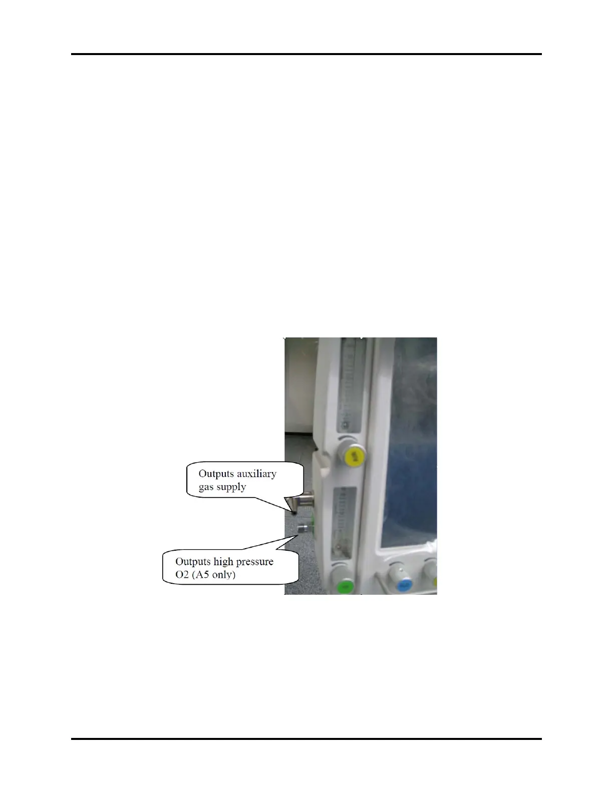
1.3.4.10 High Pressure O2 Output Assembly (A5 Only)
The high pressure O2 output (available on the A5 only) comes from the gas source directly and
provides high pressure O2 for the external ventilation device (jet ventilation devices) without passing
through the pressure regulator. When no external device is connected, the high pressure O2 output
is closed. The maximum flow is greater than 90L/min.
FIGURE 1-17 High Pressure O2 Output Assembly (A5 only)