Gas Flow Theory of Operation
1 - 26 046-001141-00 A5/A3™ Service Manual
The above picture shows the O2 flush button assembly. When the O2 flush valve (20) is depressed, O2
rushes into the pneumatic circuit, which is cut off when this valve is released. The O2 supply gas at 0.2
MPa, after being regulated, goes through the O2 flush valve, the CGO assembly, and into the
breathing system. The O2 flush button assembly is not affected by the system switch. Flushing O2
can be performed as long as O2 supply is normal. The O2 flush valve has a slide valve structure inside
that ensures automatic reset each time the valve is depressed and released via the spring.
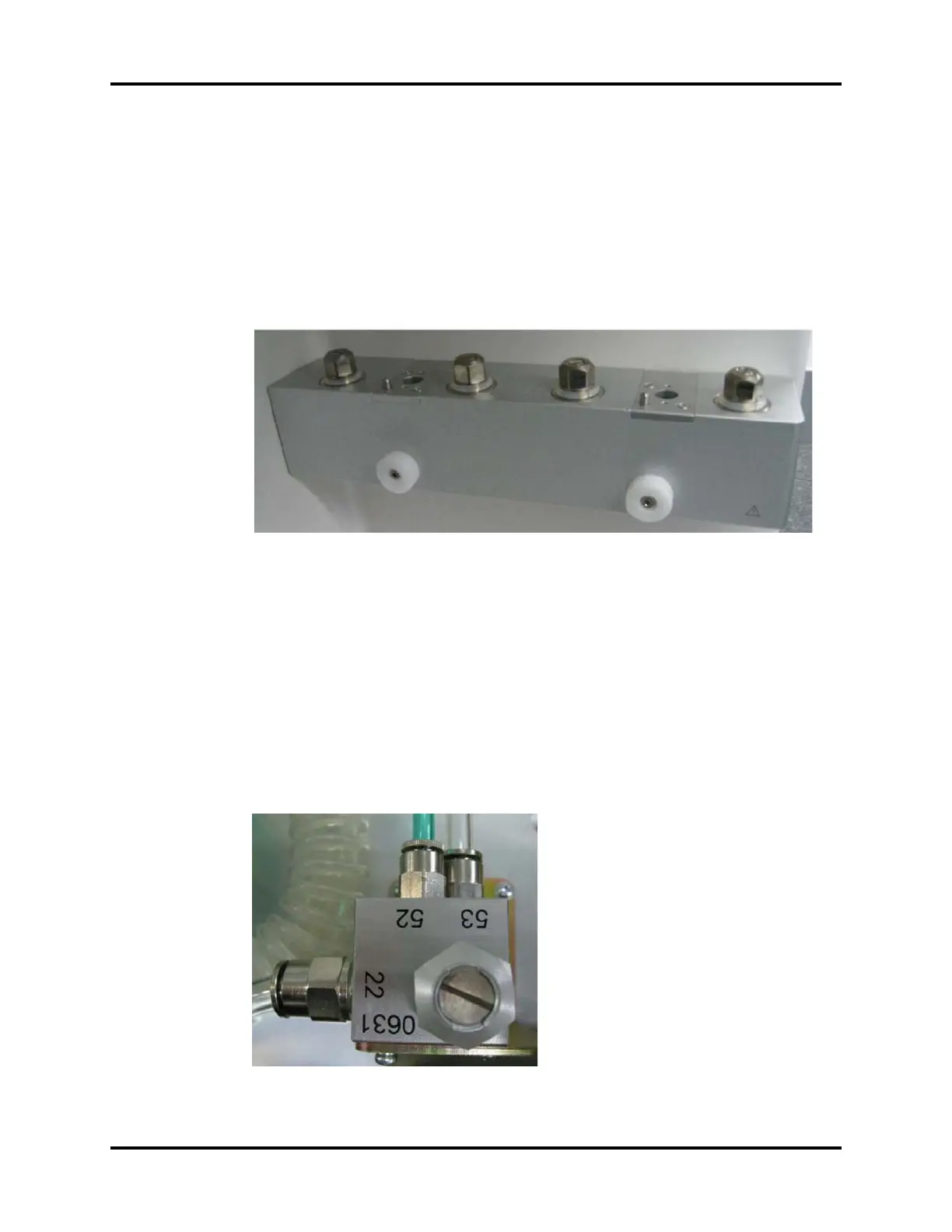
1.3.4.7 Vaporizer Manifold
FIGURE 1-15 Vaporizer Manifold
The above picture shows the vaporizer manifold assembly. The anesthetic agent delivery device
(vaporizer) is connected to the anesthetic gas delivery system. The mixed gas of N2O, O2, and Air go
into the device; the fresh gas containing these three gases and anesthetic agent is finally outputted
to the CGO assembly.
Either vaporizer manifold (27) is integrated with a check valve (28) that prevents flushed O2 and fresh
gas from flowing back to the vaporizer. The Selectatec mounting with interlocking function prevents
the user from turning on two vaporizers simultaneously.
1.3.4.8 CGO Assembly
FIGURE 1-16 CGO Assembly