EasyManuals Logo

Mindray M9 User Manual

Mindray M9
267 pages
To Next Page IconTo Next Page
To Previous Page IconTo Previous Page
Page #152 background imageLoading...
Page #152 background image
8-22 Structure and Assembly/Disassembly
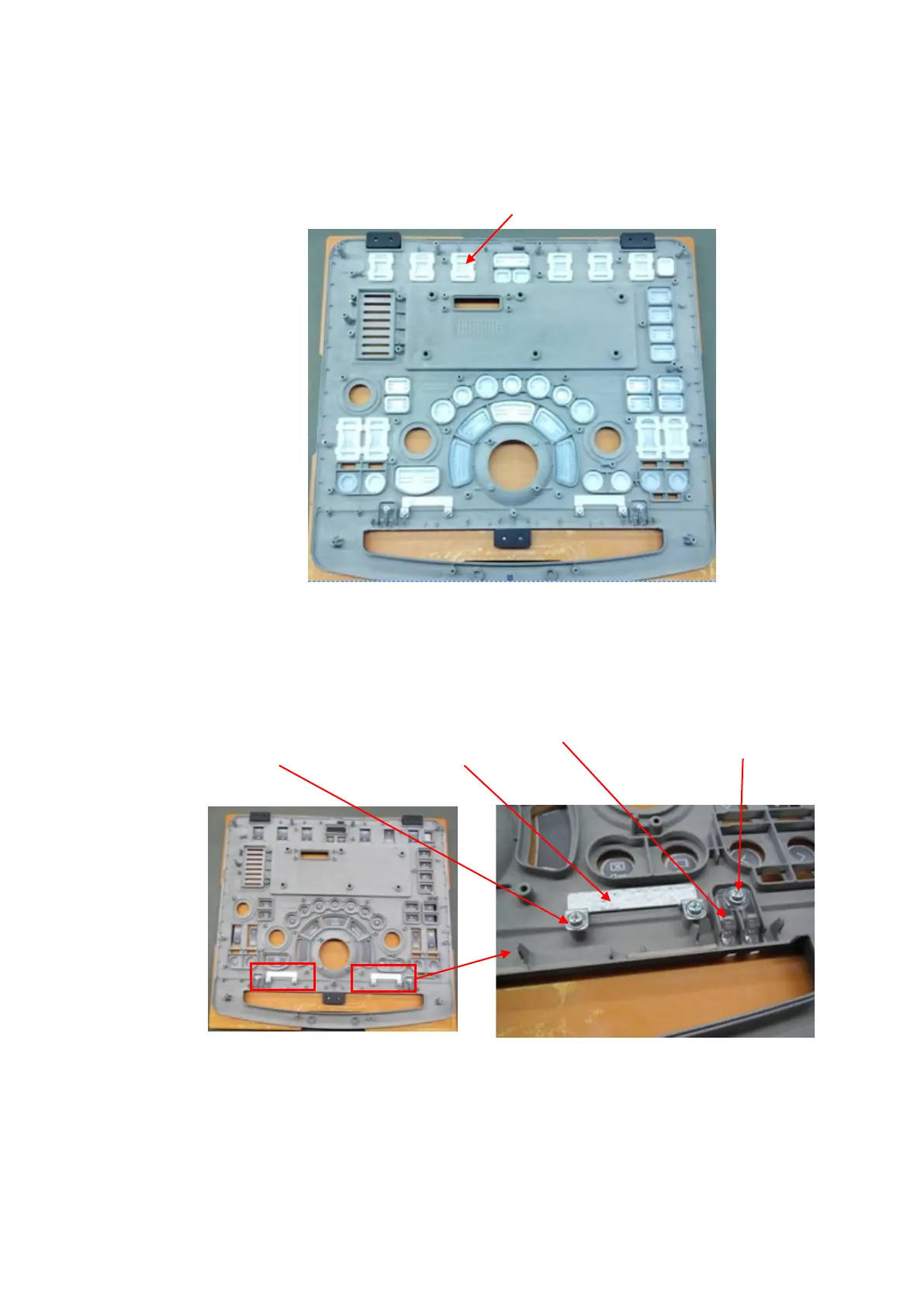
8. Disassemble caps
Remove button caps on the control panel.
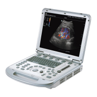
9. Disassemble magnetic induction chip and status indicator.
Unscrew 4 screws (M3 X 6 cross panhead screw, 2 screws for each left and right side) from
magnetic induction clip. Take out the magnetic chip. Unscrew 2 screws (M3 X 6 cross panhead
screw, 1 screw for each left and right side) from status indicator. Take out the status indicator.
10. Disassemble silicon keyboard
Silicon keyboard is installed on the control panel PCBA via interference fit of silicon bearings
(back of PCBA). Remove the silicon keyboard from control panel.
M3 X 6 cross panhead
screw (4 screws, 2 screws
for each left and right side)
Magnetic
induction
chip
Status
indicator
M3 X 6 cross panhead
screw (2 screws, one screw
for each left and right side)
Disassemble button caps

Table of Contents

Questions and Answers:

Question and Answer IconNeed help?

Do you have a question about the Mindray M9 and is the answer not in the manual?

Mindray M9 Specifications

General IconGeneral
TypePortable Ultrasound System
BatteryRechargeable lithium-ion battery
Battery LifeUp to 90 minutes
Display15.6 inch high resolution LED monitor
Imaging ModesB, M, Color, Power, PW, CW
TransducersLinear, Convex, Phased Array
Transducer Ports3
Probe Connectors3
ConnectivityDICOM, USB, HDMI
Operating SystemWindows-based

Related product manuals