6 Image Acquisition
Operator’s Manual 6 - 25
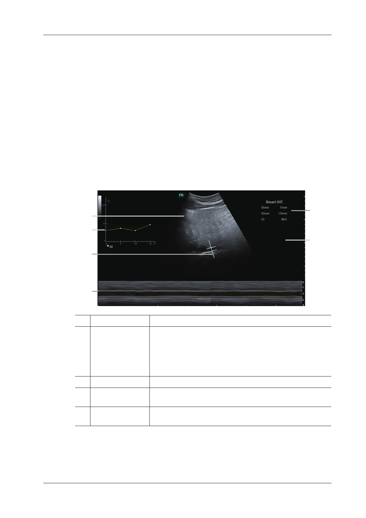
3. Tap [Smart IVC] on the touch screen or the user-defined key to enter Smart IVC mode and
start calculation.
a. Tap to select a breath type: Spontaneous Breath or Mechanical Ventilation.
b. Select [Change Resp time] > [Resp Time] to set a respiratory time.
The system measures the IVC inner diameter of the image in every frame, calculates the
maximum and minimum IVC diameters, and draws a quantitative index change curve in real
time.
4. If necessary, you can adjust the IVC sampling line manually:
a. Tap [Edit Line] on the touch screen.
b. Tap [Angle] on the touch screen to adjust the sampling line angle, and use the trackball/
trackpad to adjust the sampling line position.
c. Press the <Update> key to start calculating IVC again.
5. Press the <Freeze> key to freeze the image and finish calculating IVC.
The calculation results and quantitative trend curve are displayed on the main screen. Tap
[Diagnostic Info] on the touch screen to add diagnostic information to the image quickly.
1B Mode Image /
2IVC CI
(Collapsibility
Index), DI
(Distensibility
Index), IVCV trend
curve
Corresponds to the selected breath type:
• Autonomous Resp: displays the IVC CI curve.
• Mechanical Vent: displays the IVC DI curve and IVCV curve.
3IVC Sampling Line/
4 IVC Trending Line The horizontal axis represents the time, which is displayed in the
below Free Xros M image, and is traced along the IVC vessel wall.
5 Diagnostic
Information
Displays the added diagnostic information.
1
2
3
4
6
5
Volume
responsiveness