QMT-5302N Connections
120
QMT-5302N Connections
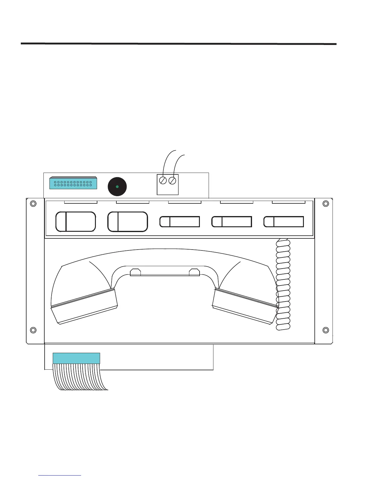
The connections required on the QMT-5302N Network Master Firefighters’ Telephone Control Module are the cable
from the previous display module to P1 or IN connector on the bottom left of the board and the OUT connection
goes to the IN connector of the next display board.
The master telephone positive and negative terminals connect to the TNC-5000 Zone 1 positive and negative
terminals with twisted shielded pair wires. Refer to Figure 86 below for connector and terminal block locations of the
QMT-5302N.
Figure 86: QMT-5302N Cable Connection and Terminal Wiring
- +
Connection from previous display
Connection to Telephone
Selector Panel P1 or next display
IN
OUT
To TNC-5000 Telephone Zone 1
positive and negative terminals
(twisted shielded pair wire)
DESELECT ALL
CALL CONTROL
ACTIVE
CALL CONTROL
TROUBLE INCOMING CALL
P1
P2