Field Wiring
52
FNC-2000 Fire Network Controller Module
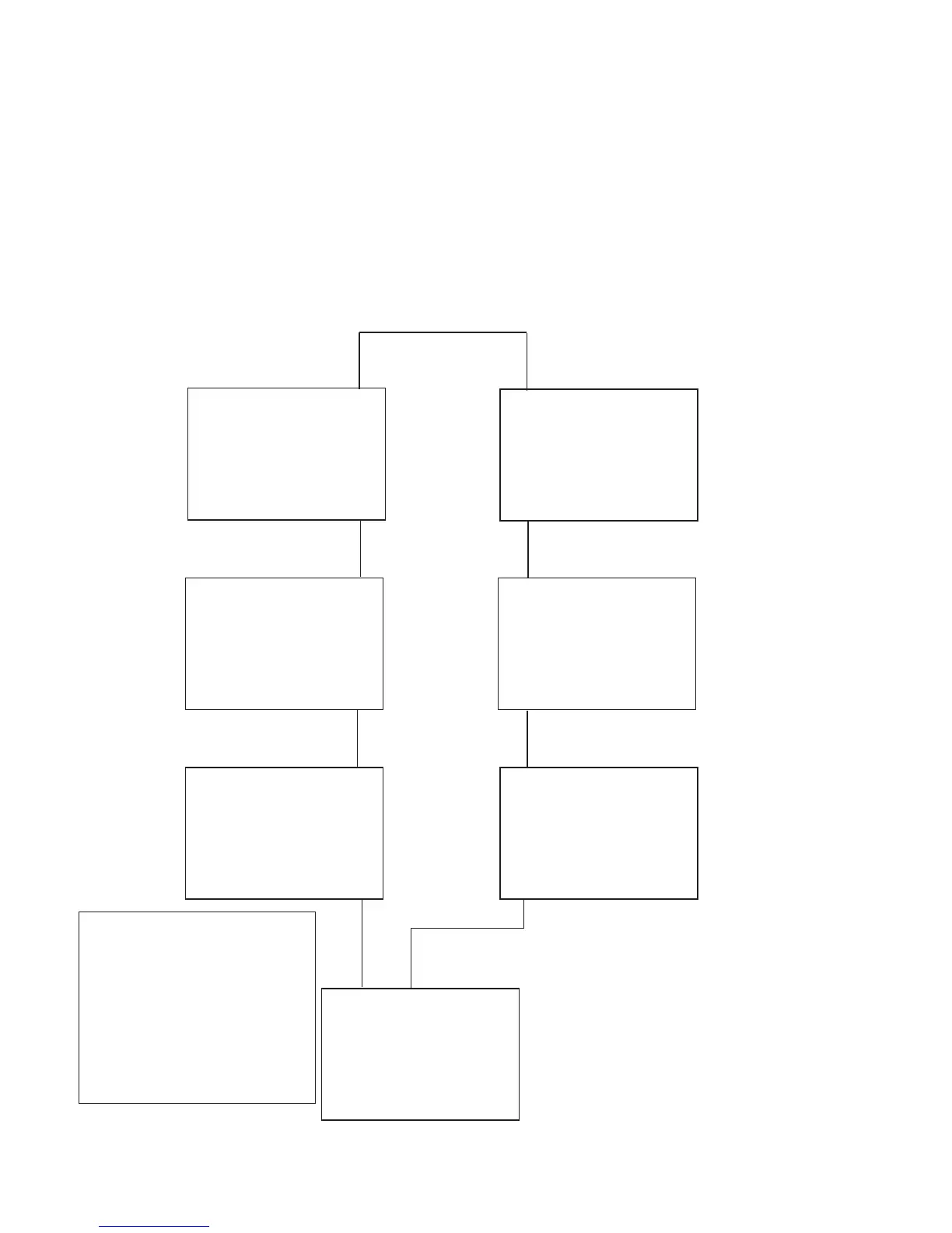
The FNC-2000 Fire Network Controller modules are wired from terminals marked Line A, positive and negative (see
specific cable recommended in Figure 37) to the Line B terminals of the next FNC-2000 module. Use of shielded
cable is not recommended. Wire from Line B terminals to Line A of the next FNC-2000 module. Start from the
lobby panel and wire to all the FNC-2000, wiring the last FNC-2000 back to Line B of the first FNC-2000 at the lobby
panel for Class A.
Figure 37: Style 7 Wiring for the FNC-2000 Module
Line B
Line A
Line A
Line A
Line A
Line A
Line A
Line A
Line B
Line B
Line B
Line B
Line B
Line B
FNC-2000
Lobby Panel
FNC-2000
FNC-2000
FNC-2000
FNC-2000
FNC-2000
FNC-2000
STYLE 7 WIRING
RECOMMENDED CABLE:
BELDEN 5320 UJ or 5320UM
Tyco Pyro CIC
Draka Lifeline
All above cables are 2x18AWG unshielded,
low capacitance
Network Wiring Specifications
Power-Limited and Supervised
Voltage: 9V Max
Current: 800mA
Frequency: 625K Hz
Line Loss: 25 ohms
4000 feet MAX wiring distance
with twisted pair 18 gauge wire.