FleX-Net
TM
Installation and Operation Manual
81
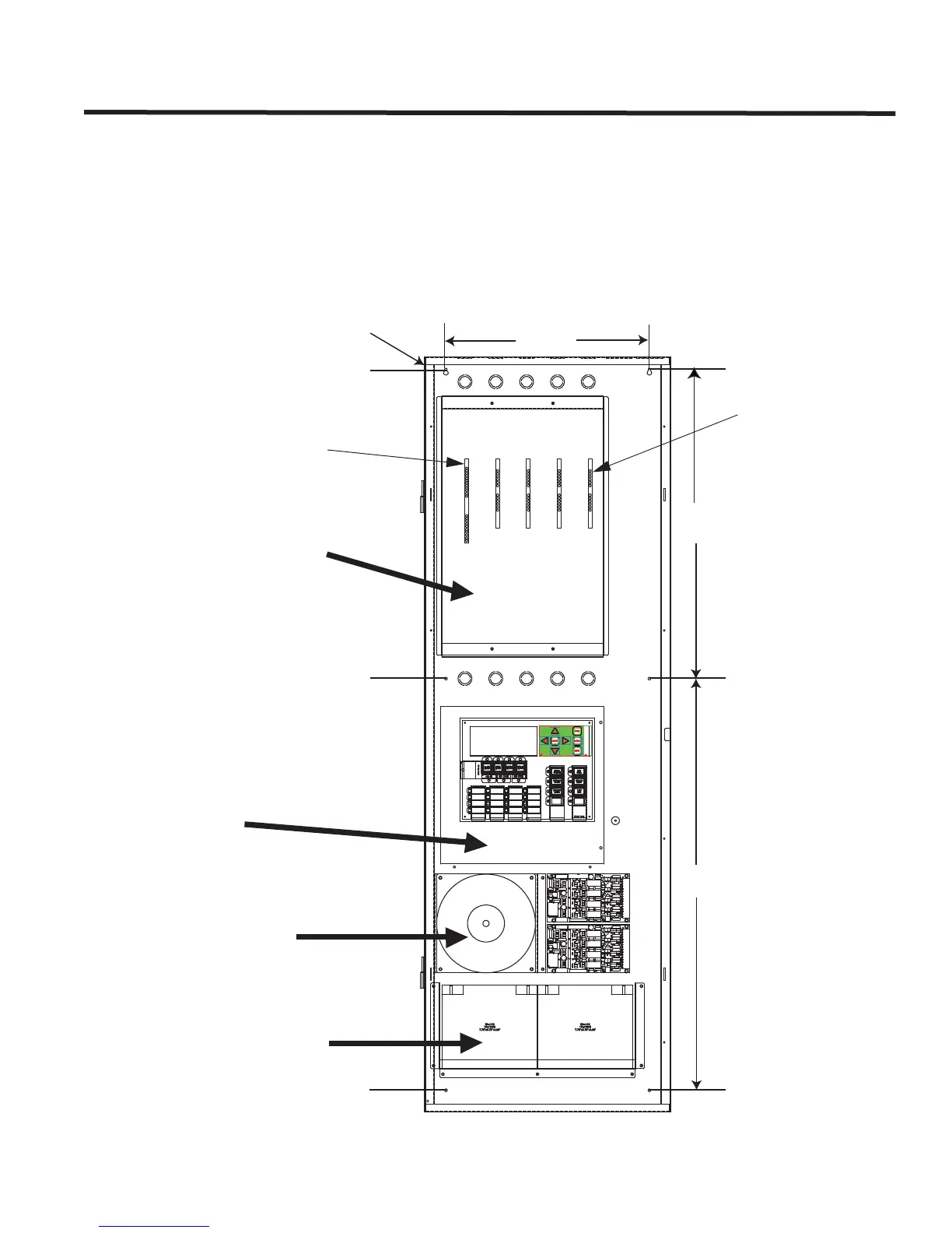
Integrated Fire/Audio Cabinet Mechanical Installation
The Integrated Fire/Audio Cabinet is the network fire alarm and audio floor or node panel. It is mounted into the
BBX-2000 backbox and door. Mount the backbox onto the wall using six #8 screws to secure the backbox to the
wall. The backbox is surface mounted only; the dimensions for the mounting holes are shown in Figure 54 below.
The Integrated Fire/Audio Cabinet consists of the Audio Card Cage, FX-2000ND Deep Chassis with FX-2000N
Main Control board/2 Amp Battery Charger, and PS-2040 10 Amp Fire Alarm/30 Amp Audio Power Supply.
Batteries are mounted in the tray located at the bottom of the enclosure.
Figure 54: BBX-2000 Enclosure with the Integrated Fire and Audio System
16.5”16.5”
25” 25”
33.5” 33.5”
BBX-2000 Enclosure
QMB-5000N Audio Card Cage
FX-2000ND Main Chassis with
provision to mount FNC-2000
Network Controller Module and
2 adder modules/loop controllers
PS-2040 Power Supply and space
to mount 6 adder modules/
loop controllers
Batteries (maximum 40 AH)
Metal plate with ANC-5000 and
TNC-5000 modules aboard fit
into position 1 of the QMB-
5000N Audio Card Cage
QAA Amplifiers fit
into slot positions 2,
3, 4 and 5.