FleX-Net
TM
Installation and Operation Manual
85
Integrated Fire/Audio Cabinet - Audio Module Placement and
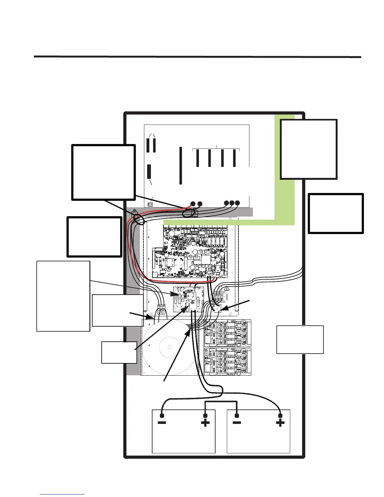
Internal Wiring
The modules that mount into the Integrated Fire/Audio Cabinet audio card cage are the amplifier modules. Up to
four amplifiers may be installed in each Integrated Fire/Audio Cabinet with one of the four as a backup. Slot #1 is
used for the ANC-5000 and/or TNC-5000 modules.
Figure 57: Integrated Fire/Audio Cabinet Internal Power Wiring.
12 VDC BATTERY
12 VDC BATTERY
BATTERY
Orange-White-Orange
(MUST BE IN CORRECT ORDER)
TRANSFORMER
Black
IN OUT
Red
Red
CONNECTORS FOR MULTIPLE
QMB- 5000N EXPANSION CARD CAGES
SLOT #1 CONNECTOR
ANC-5000 BOARDS
FOR TNC-5000 AND
SLOTS #2 - #5
CONNECTORS FOR
QAA- STYLE AMPLIFIERS
CONNECTOR
AND TERMINALS
NOT USED
+
-
Drawing not to
scale. Boards
enlarged to show
required wiring.
Red (positive) and Black (negative) wires
from the Amplier backplane (soldered
on board) are connected to lug terminals
on the Battery Disconnect board
Orange-White-Orange
Wires connected from
the transformer
to this terminal block
Connected to Batteries
Battery Fuse F1
32V, 40A MAX
Fast-acting
AC Power IN
G N 120VAC
or 240VAC
Wire as per label.
Two brown wires
connected from the
transformer to the
bridge rectier.
Green (GND), black (N), red (120V AC)
and yellow (240V AC) wires connected
from the transformer to the AC Input
Terminals.
-
-
-
-
-
+
+
+
+
+
Drawing is shown for
clarity of connections.
Required separation of
non-power limited
and power limited
wiring must be
provided with barriers
or nonconductive
sleeving.
Use wire ties secured to
the backbox, in positions
as shown, to assure that
these NON POWER-
LIMITED wires remain
at least 1/4 inches away
from wires that are
connected to POWER-
LIMITED circuits.
Battery
Disconnect
Board
Gray Area marks
the location for
all non-power
limited wiring.
Right side of
box is reserved
for all power
limited wiring.
Battery
Disconnect
Board has a
replaceable
fuse: F1 is a
fast acting
32V 40A
Fuse.