FleX-Net
TM
Installation and Operation Manual
27
Module Settings
Main Fire Alarm Module (MD-871A “N” Version Main Chassis)
This main board has one addressable loop and network capability.
JW1 Jumper is removed if a PR-300 or UDACT-300A is installed.
JW2,JW4 Jumpers are Factory Set and should not be changed.
JW5 Normally un-installed, add jumper to silence on-board buzzer.
JW6 Normally installed, remove jumper to enable external power supply supervision.
P1,2 Factory connection to Bridge Rectifier.
P3 Black RS-485 Connector connects to the Adder Loop ALCN-792M if used (Address Loops 3 and 4)
P4 Connector for PR-300 Module or UDACT-300A.
P5 Connector for next 8 Conventional Hardwire Circuit Adder Modules (Loop 1).
P6 Connector for first 8 Conventional Hardwire Circuit Adder Modules (Loop 0).
P7 Ethernet jack.
P8 Power Connector for Adder Modules.
P9 RS-232C for Printer or “CRT” Monitor.
P10,11 Connection to 24 VDC Battery. Observe Polarity.
P14 Connector for Display Module.
P15, P18, J1 Connectors for Factory Use.
P16 High speed RS-485 audio link to ANC-5000 Audio Network Controller Module.
When connected provides ARCnet or Fibre Optic audio and telephone communication
P19 Connector for FNC-2000 Fire Network Controller Module.
SW2 DIP Switch for node address.
NAC PWR 24V FWR input terminals for additional power for signal adder modules.
F1 20 Amp slow blow non-replaceable fuse.
TO CONFIGURE THE FIRE ALARM PANEL USE THE RS-485 CONNECTOR P4 OF THE LAST ADDER LOOP
CONTROLLER MODULE INSTALLED OR IF NOT PRESENT, P3 ON THE FleX-Net
TM
MAIN FIRE ALARM MODULE.
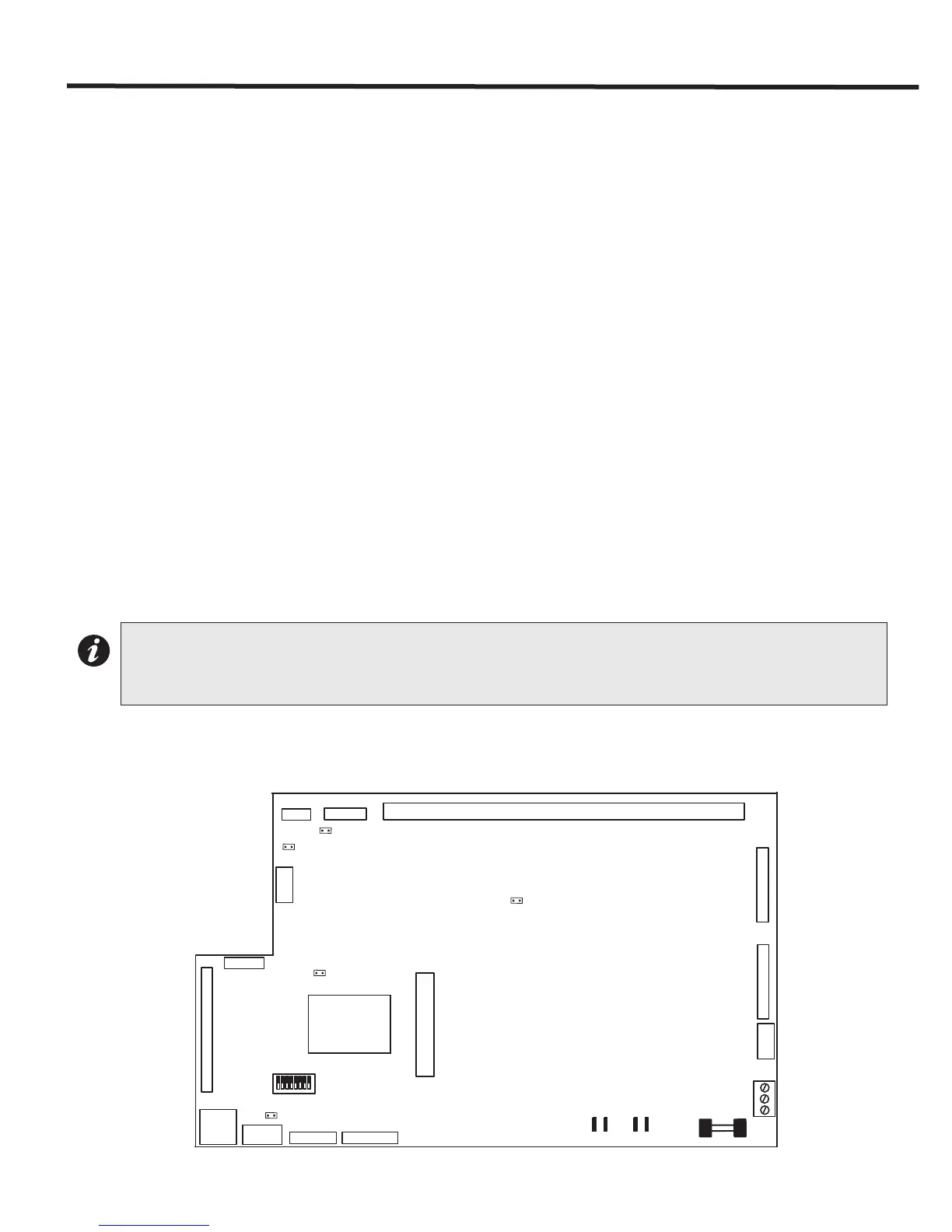
Figure 11: Main Fire Alarm Module (MD-871A “N” Version Main Chassis)
Note: To enable communication from the Main Module to all of the Adder Modules, it is necessary to add a Continuity
Jumper on the last Adder Module in a chain (see the appropriate Module Settings section to verify the location of
the Continuity Jumper on a particular Circuit Adder Module). Only the last circuit adder module should have a
jumper plug on its continuity jumper; all others must be left without a jumper plug.
F1
MAIN FIRE ALARM BOARD
FIELD WIRING TERMINALS
P3
P2
P1
P18
P16
P10 P11
P15
P4
J1
P9
P7
P5
P6
P8
+ BR - +BAT -
NAC PWR
P14
P19
JW1
JW4
JW5
JW6
JW2
SW2
1
8
ON